Unlock instant, AI-driven research and patent intelligence for your innovation.

Hula seal

Active Publication Date: 2017-06-22
ANSALDO ENERGIA SWITZERLAND AG
View PDF0 Cites 0 Cited by
  • Summary
  • Abstract
  • Description
  • Claims
  • Application Information

AI Technical Summary

Benefits of technology

The hula seal described in this patent can reduce stress and failure in high-temperature gas turbine components. It does this by using a hula seal made of a single piece of material that can better tolerate expansion and contraction in the circumferential direction, reducing the likelihood of cracks and improving sealing efficiency. Additionally, the hula seal can have a slit to further reduce fatigue. Connecting the leaves at both ends can also help avoid trapping and crumpling during assembly. Overall, this hula seal design can improve performance and durability of gas turbine components.

Problems solved by technology

While hula seals such as that shown in FIG. 1 can provide good seals, a number of limitations have been appreciated.
One particular issue lies with stress cracks.
As a result of the differing materials and temperature variations during use of the gas turbine, the welds connecting the hula seal to the part can easily crack or fatigue cracks can occur in the hula seal.

Method used


Image

  • Hula seal
  • Hula seal
  • Hula seal

Examples


Embodiment Construction

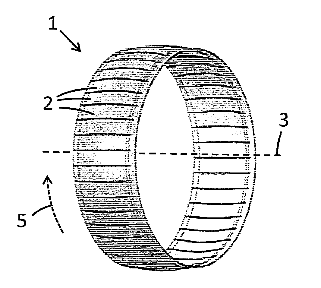
[0024]FIG. 2 shows part of a hula seal 10, extending from a first edge 12 to a second edge 14 in an axial direction 4 and extending in a circumferential direction 5. The hula seal is divided into leaves 20, 21 by slits 22 in between the leaves. The slits extend in the axial direction, but do not reach either edge. At each edge there is an edge region 13, 15 between the edge 12, 14 and the end of the slit 22. At each end of each slit, an end slit 24 extends perpendicular to the axial direction (and therefore parallel to the circumferential direction). Overall, each slit is therefore an I shape. In FIG. 2, the hula seal is shown in its unfolded state; this will be explained in more detail below.

[0025]FIG. 3 shows the view from the line I-I in the hula seal of FIG. 2. The width of a leaf 21 in the radial direction 6 can be seen, along with the curvature of the leaves in the axial direction 4. The dotted lines in FIG. 2 show the extent of this curvature (and therefore the extent of the ...


PUM


Abstract

A hula seal as disclosed extends in a circumferential direction, a radial direction and an axial direction relative to a central axis. The hula seal includes a first leaf extending from the first edge region to the second edge region and a second leaf extending from the first edge region to the second edge region. The first leaf is the same distance as the second leaf from the central axis in the radial direction, and is adjacent to and overlaps the second leaf in the circumferential direction, when installed in a gas turbine. The first leaf is attached to the second leaf such that the first leaf can move relative to the second leaf in the circumferential direction when installed in a gas turbine.

Description

TECHNICAL FIELD[0001]The present disclosure relates to hula seals, and particularly to hula seals with leaves that overlap one another when installed in a gas turbine.BACKGROUND OF THE INVENTION[0002]Hula seals are used in various places in gas turbines to seal gaps between adjacent gas turbine parts. FIG. 1 shows an existing hula seal 1. The hula seal comprises a plurality of leaves 2 extending around the circumference relative to a central axis 3. While hula seals such as that shown in FIG. 1 can provide good seals, a number of limitations have been appreciated. One particular issue lies with stress cracks. A hula seal may be made of a different material to the part to which it is attached. However, the temperature range that a hula seal is subjected to can easily be hundreds of degrees (e.g. from ambient temperature to 800 degrees Celsius). As a result of the differing materials and temperature variations during use of the gas turbine, the welds connecting the hula seal to the pa...

Claims


Application Information

Patent Timeline
IPC IPC(8): F01D11/00F23R3/00F16J15/08F02C7/28
CPCF01D11/003F02C7/28F05D2240/57F16J15/0887F05D2220/32F23R3/002F01D11/005F05D2250/184F05D2250/294F23R3/60F23R2900/00012
Inventor STEINER, HARALDSMIRNOVA, YULIA
Owner ANSALDO ENERGIA SWITZERLAND AG