Component pickup position correction system and component pickup position correction method for a rotary head type component mounter

a technology of component mounter and pickup position correction system, which is applied in the direction of electrical components, electrical apparatus, etc., can solve the problems of picking up errors and the like more likely to occur, and achieve the effect of accurately calculating the xy direction movement amount and rotation angle, and accurately calculating the position

Active Publication Date: 2017-10-26
FUJI MASCH MFG CO LTD
View PDF4 Cites 5 Cited by
  • Summary
  • Abstract
  • Description
  • Claims
  • Application Information

AI Technical Summary

Benefits of technology

[0011]Even in cases in which the positions of the leading components in component supply tape set in two tape feeders are deviated, or in which the positions of two suction nozzles used to pick up those components are deviated, with the present disclosure, because the rotary head is moved in the XY directions and rotated such that the pickup points of the two suction nozzles are positioned on two straight lines extending in the tape feeding direction of each tape feeder passing through an ideal pickup point of the leading components of the two tape feeders, and the leading components are fed to the component pickup positions that are the pickup points of the suction nozzles on the two straight lines by performing tape feeding operation of the two tape feeders, it is possible to pick up the components at two component pickup positions simultaneously by lowering the two suction nozzles simultaneously, thereby improving productivity.
[0012]With the present disclosure, position data of multiple suction nozzles that is measured in advanced may be memorized on a memory device, and a calculating device may calculate an XY direction movement amount and rotation angle of the rotary head required to move to the component pickup positions of the two tape feeders and a tape feeding amount of the two tape feeders, based on the positions of the ideal pickup points of the leading components of the two tape feeders and the positions of the two suction nozzles obtained by searching for the position data of the two suction nozzles used to pick up the leading components from the two tape feeders from the position data memorized on the memory device. According to this, it is possible to simply and accurately calculate the positions (the two component pickup positions) of the pickup points of the two suction nozzles on the straight lines based on the geometrical positional relationship between the positions of the two pickup nozzles that are to pick up the two components, and the positions of the ideal pickup points of the two leading components, and it is possible to simply and accurately calculate the XY direction movement amount and rotation angle of the rotary head required to move to the two component pickup positions and the tape feeding amount of the two tape feeders.

Problems solved by technology

When a component mounter picks up a component supplied from a tape feeder with a suction nozzle, if the component pickup position is deviated, pickup errors and the like are more likely to occur, making it necessary to perform correction to align the position of the suction nozzle with the position of the next component to pick up.

Method used


Image

  • Component pickup position correction system and component pickup position correction method for a rotary head type component mounter
  • Component pickup position correction system and component pickup position correction method for a rotary head type component mounter
  • Component pickup position correction system and component pickup position correction method for a rotary head type component mounter

Examples


Embodiment Construction

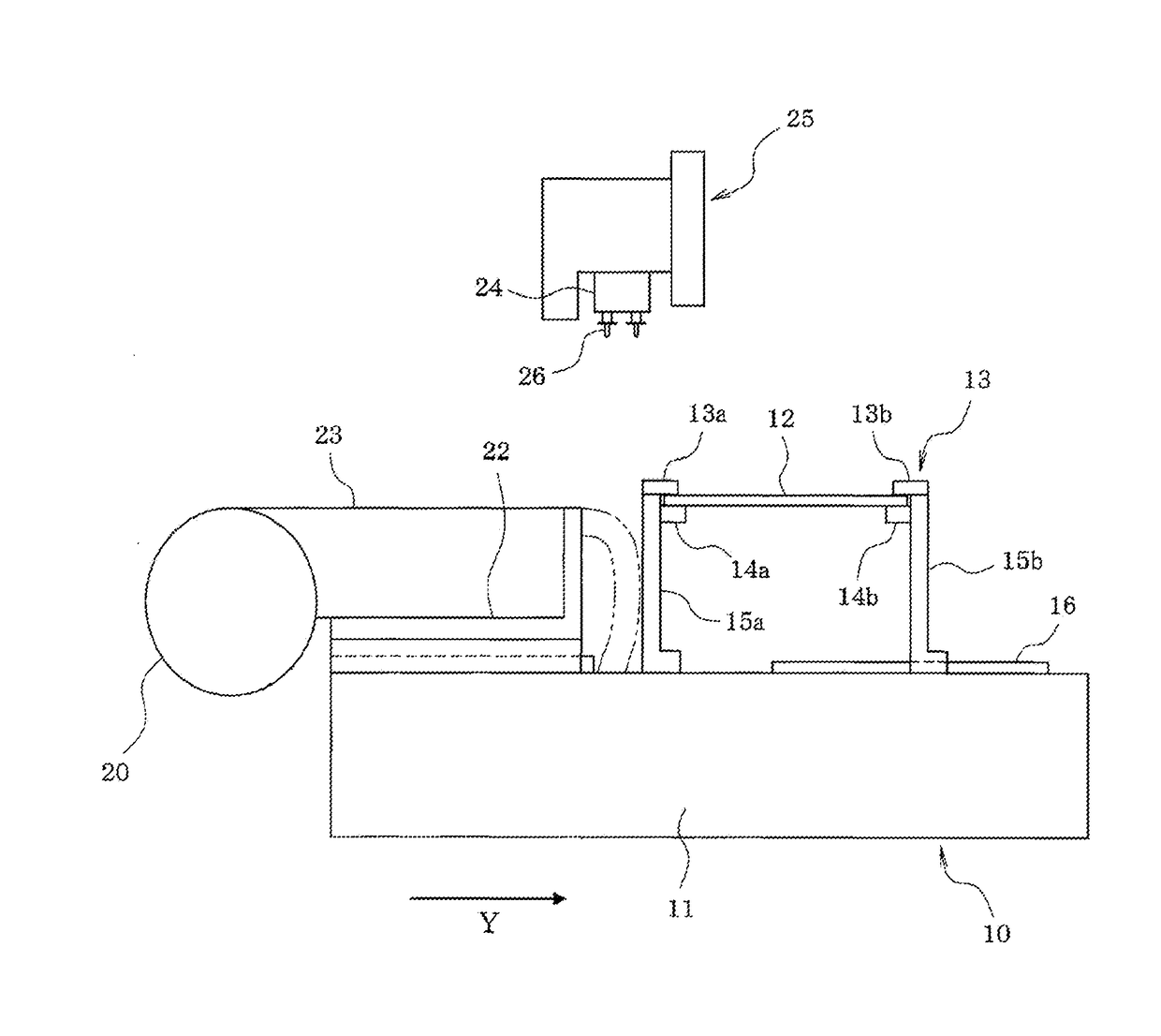
[0021]An embodiment of the disclosure is described below. First, the configuration of rotary head type component mounter 10 is described based on FIGS. 1 and 2.

[0022]Conveyor 13 that conveys circuit board 12 is provided on base 11 of rotary head type component mounter 10 (below, the conveyance direction of circuit board 12 by conveyor 13 is referred to as the X direction). Of support members 15a and 15b that support the two conveyor rails 13a and 13b and conveyor belts 14a and 14b that configure conveyor 13, support member 15a is fixed at a specified position, with the support member 15b on the opposite side being adjusted in the Y direction (positioned perpendicular to the X direction) along guide rail 16 by a feed screw mechanism (not shown) or the like such that the width of conveyor 13 (the gap between conveyor rails 13a and 13b) is adjustable to the width of circuit board 12.

[0023]Further, device pallet 22 (feeder setting table) is detachably attached on base 11 to the side of ...


PUM

PropertyMeasurementUnit
angleaaaaaaaaaa
rotation angleaaaaaaaaaa
sizesaaaaaaaaaa

Abstract

In a rotary head type component mounter, before using two suction nozzles of rotary head to pick up the leading components in component supply tape set in two tape feeders, rotary head is moved in the XY directions by head moving mechanism and rotated by head rotating mechanism such that the pickup points of the two suction nozzles are positioned on two straight lines and extending in the tape feeding direction of each tape feeder passing through the ideal pickup points of the leading components of the two tape feeders, and the leading components are fed to component pickup positions and that are the pickup points of the suction nozzles on the two straight lines. Then, the two suction nozzles of rotary head are lowered simultaneously to pick up the two component simultaneously using the two suction nozzles.

Description

TECHNICAL FIELD[0001]The present application relates to a component pickup position correction system and component pickup position correction method for a rotary head type component mounter provided with a function that corrects the position at which to pick up a component that is supplied by a tape feeder.BACKGROUND ART[0002]When a component mounter picks up a component supplied from a tape feeder with a suction nozzle, if the component pickup position is deviated, pickup errors and the like are more likely to occur, making it necessary to perform correction to align the position of the suction nozzle with the position of the next component to pick up. Thus, conventionally, correction is performed to align the position of the suction nozzle with the position of the next component to pick up (a target component pickup position) by moving the mounting head that holds the suction nozzles in the XY directions (left-right and front-rear directions).[0003]Further, with a rotary head typ...

Claims


Application Information

Patent Timeline
Patent Type & Authority Applications(United States)
IPC IPC(8): H05K13/04H05K13/02
CPCH05K13/02H05K13/0408H05K13/0413H05K13/0417H05K13/041Y10T29/49137Y10T29/53174Y10T29/53191
Inventor ITO, HIDETOSHIIISAKA, JUN
Owner FUJI MASCH MFG CO LTD
Why Eureka
Try Eureka