Heat exchanging ventilation device

Active Publication Date: 2018-08-09
PANASONIC INTELLECTUAL PROPERTY MANAGEMENT CO LTD
View PDF5 Cites 0 Cited by
  • Summary
  • Abstract
  • Description
  • Claims
  • Application Information

AI Technical Summary

Benefits of technology

[0011]As a result, the heat exchanging ventilation device can eliminate de

Problems solved by technology

In such a heat exchanging ventilation device of the related art, when a temperature of outdoor air decreases in winter, air exhausted from the room is cooled by a heat exchange element and there is a problem that moisture contained in the exhausted air is dew-condensed or frozen.
In order to pr

Method used


Image

  • Heat exchanging ventilation device
  • Heat exchanging ventilation device
  • Heat exchanging ventilation device

Examples


Example

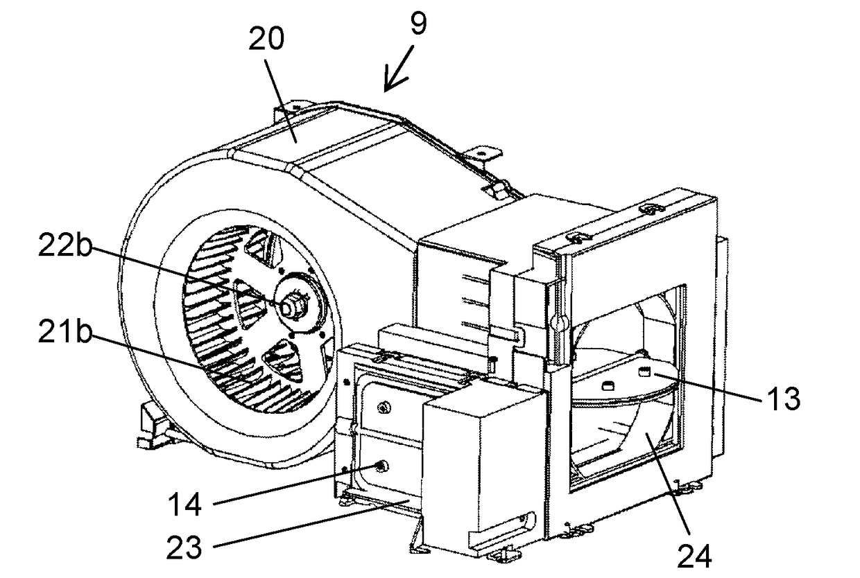
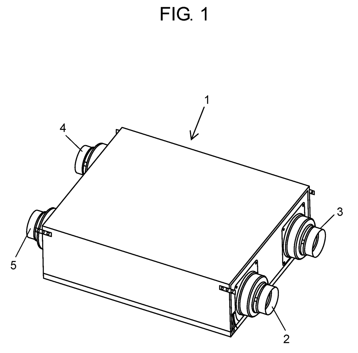
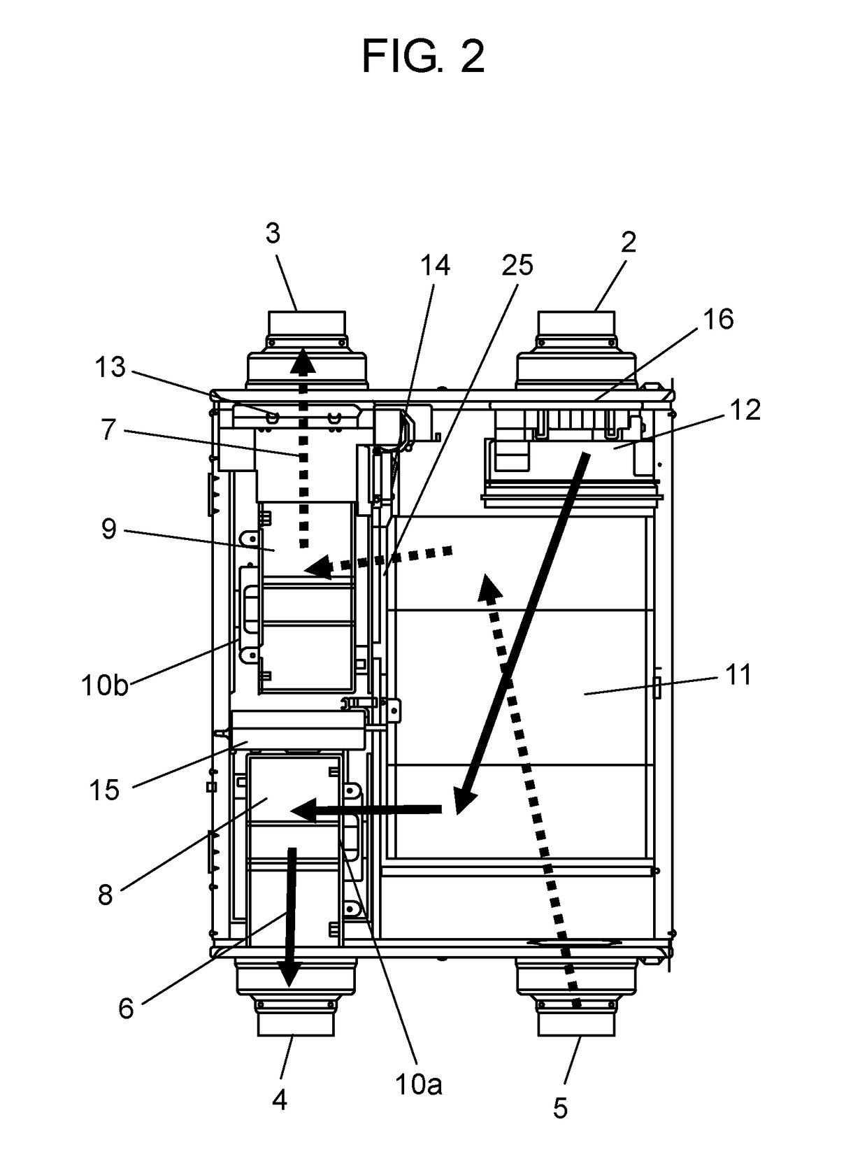
[0018]According to an aspect of the invention, there is provided a heat exchanging ventilation device including a supply air blower; an exhaust air blower; a supply air blowing passage that is a passage through which air to be delivered to indoor from outdoor by the supply air blower passes; an exhaust air blowing passage that is a passage through which air to be delivered to the outdoor from the indoor by the exhaust air blower passes; a heat exchange element disposed at a position where both the supply air blowing passage and the exhaust air blowing passage pass and exchanging heat between air delivered by the supply air blower and air delivered by the exhaust air blower; a supply air damper provided on a supply air inlet side of the supply air blowing passage; an exhaust air damper provided on the exhaust air outlet side of the exhaust air blowing passage; air blowing passage and a circulation damper provided at a boundary portion which separates the supply air blowing passage an...


PUM


Abstract

A heat exchanging ventilation device includes supply air blower (8); exhaust air blower (9); a supply air blowing passage through which air to be delivered to indoor from outdoor by supply air blower (8) passes; a exhaust air blowing passage through which air to be delivered to the outdoor from the indoor by the exhaust air blower passes; heat exchange element (11) disposed at a position where both the supply air blowing passage and the exhaust air blowing passage pass and exchanging heat between air delivered by supply air blower (8) and air delivered by exhaust air blower (9); supply air damper (12) provided on supply air inlet (2) side of the supply air blowing passage; exhaust air damper (13) provided on exhaust air outlet (3) side of the exhaust air blowing passage; and circulation damper (14) provided at boundary portion (25) which separates the supply air blowing passage and the exhaust air blowing passage from each other.

Description

TECHNICAL FIELD[0001]The present invention relates to a heat exchanging ventilation device that exchanges heat between outdoor air and indoor air.BACKGROUND ART[0002]In the related art, as a heat exchanging ventilation device of this type, a heat exchanging ventilation device, which is installed in a building, introduces outdoor air from an outdoor air supply port, and supplies the outdoor air into a room via a built-in heat exchange element, is known (for example, see PTL 1).[0003]Hereinafter, the heat exchanging ventilation device will be described with reference to FIG. 6.[0004]FIG. 6 is a view for explaining a heat exchanging ventilation device of the related art.[0005]As illustrated in FIG. 6, ventilator main body 101 is installed in a roof rear space or a ceiling rear space in a building. Fresh air outside the room is introduced from outdoor air supply port 102, passes through heat exchange element 103 built in ventilator main body 101, and is supplied into the room via indoor...

Claims


Application Information

Patent Timeline
IPC IPC(8): F24F7/08F24F13/30F24F13/20F24F13/14
CPCF24F7/08F24F13/30F24F13/20F24F13/1413F24F13/14F24F12/006Y02B30/56
Inventor IIO, KOUJIISHIGURO, KENICHIHASHIMOTO, TOSHIHIKOSUZUKI, YASUHIRO
Owner PANASONIC INTELLECTUAL PROPERTY MANAGEMENT CO LTD
Why Eureka
Try Eureka