Rack structure for an in-field 3D construction printer

Active Publication Date: 2018-08-16
YINGCHUANG BUILDING TECH SHANGHAI CO LTD
View PDF0 Cites 4 Cited by
  • Summary
  • Abstract
  • Description
  • Claims
  • Application Information

AI Technical Summary

Benefits of technology

The invention provides a rack structure for a 3D construction printer that can elevate the print head as the building height increases, while also reducing the distance cement mortar needs to be transported. The printing platform and power and material storage platform are on different floors, allowing for the continuous printing of the 3D print head and material supply. This innovation makes a significant progress in the industry and helps achieve continuous construction.

Problems solved by technology

For insulation and exterior wall decoration, it is necessary to is provided with up a scaffold, however bring such scaffold structure can complicate a construction procedure, cause long construction time and create heavy material wasting.
But this is not a field print, and it is still a distance away from a truly 3D printed building.
Even for the buildings printed on the spot in the field, following problems occurs.
For example, 3D printing head has to rise as the height of the building increases, so far there is not a good method to achieve the height management, therefore the current 3D printed building is only limited to one or two floors in height.
Another prominent issue is that the cement concrete mortar required by the 3D printing has even poorer ability to flow and is more difficult to transport, compared with cement concrete mortar used in the traditional process.
In addition, simultaneous construction of water and electricity equipment and a series of other issues have yet to be resolved.

Method used


Image

  • Rack structure for an in-field 3D construction printer
  • Rack structure for an in-field 3D construction printer
  • Rack structure for an in-field 3D construction printer

Examples


Embodiment Construction

[0015]This invention will be further described in combination with the embodiments below.

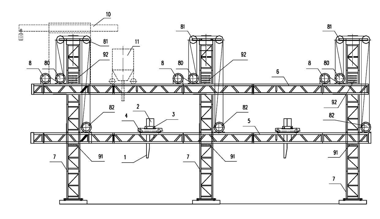
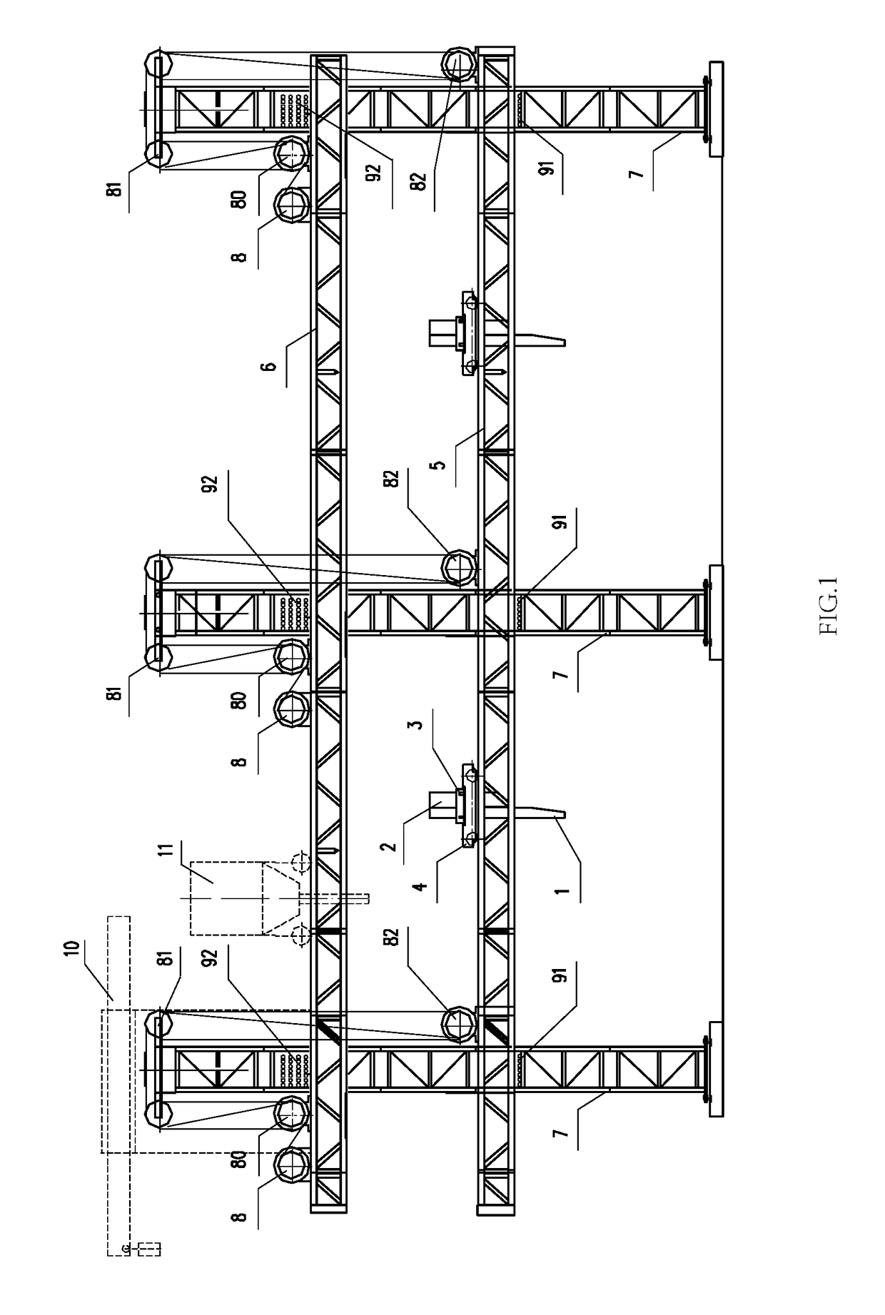
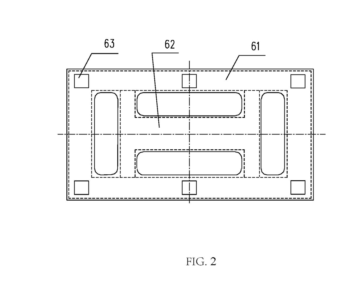
[0016]FIG. 1-2 are schematic diagrams illustrates one embodiment in this invention. In these figures, the rack structure for one in-field 3D construction printer includes vertical supporting post 7 consisting of standard vertical supporting post segments, connected to each other, in two rows with symmetrical arrangement, a horizontal slide pair 4 of the print head 1, a longitudinal slide pair 3 of the print head 1, a vertical slide pair of the print head 1, the printing platform 5, power and material storage platform 6, and the lifting mechanism.

[0017]Said printing platform 5 is a circular frame formed by the horizontal and longitudinal beams, and the two horizontal beams are provided with cavies configured to from slide pairs with the corresponding vertical supporting posts 7. The longitudinal two sides of each cavity are provided with the seating holes 91 for anchoring the horizontal beams on ...


PUM


Abstract

This invention discloses a rack structure for an in-field 3D construction printer, which comprises the vertical supporting posts consisting of connected standard vertical supporting post segments in two rows with symmetrical arrangement, a printing platform, a power and material storage platform, and lifting mechanism; said two rows of the vertical supporting posts are symmetrically arranged and fixed on the ground; the printing platform, and the power supply and material storage platform are fixed on the vertical supporting post through their respective cavities, and then the printing platform and the power and material storage platform are bolted on the vertical supporting post; the steel wire rope runs through a lifting drum, to a pulley block on the side of the power supply and material storage platform, and then from the intermediate pulley block to the pulley block on the side of the printing platform.

Description

CROSS REFERENCE TO RELATED APPLICATION[0001]This application claims priority to a Chinese Application No. 2017100725461, filed on Feb. 10, 2017. The Chinese Application is incorporated herein by reference in its entirety.TECHNICAL FIELD[0002]This invention involves a building construction machinery, specifically the rack structure for an in-field 3D construction printer.[0003]Background technology[0004]In the existing technology, the construction of an exterior wall, insulation and exterior wall decoration for most buildings is basically implemented in steps. During exterior wall construction, the interior / exterior molds are required. For insulation and exterior wall decoration, it is necessary to is provided with up a scaffold, however bring such scaffold structure can complicate a construction procedure, cause long construction time and create heavy material wasting. In recent years, with the progress of digital technology, some building members can be implemented with a 3D printi...

Claims


Application Information

Patent Timeline
IPC IPC(8): E04G21/04B28B1/00
CPCE04G21/04B28B1/001B33Y30/00B33Y40/00E04B1/35E04B1/16E04G21/00E04G21/0427E04G21/0463
Inventor MA, YIHE
Owner YINGCHUANG BUILDING TECH SHANGHAI CO LTD
Why Eureka
Try Eureka