

Double-acting pneumatic pump
a pneumatic pump and double-action technology, applied in the direction of piston pumps, positive displacement liquid engines, machines/engines, etc., can solve the problems of consuming energy and wear down of components, affecting the flow rate of fluid, and the conventional pump that needs to be solved, so as to achieve a flexible flow rate and easy and accurate control
- Summary
- Abstract
- Description
- Claims
- Application Information
AI Technical Summary
Benefits of technology
Problems solved by technology
Method used
Image

Examples
Embodiment Construction
[0017]Hereinafter, an exemplary embodiment of the present invention will be described in detail with reference to the accompanying drawings.
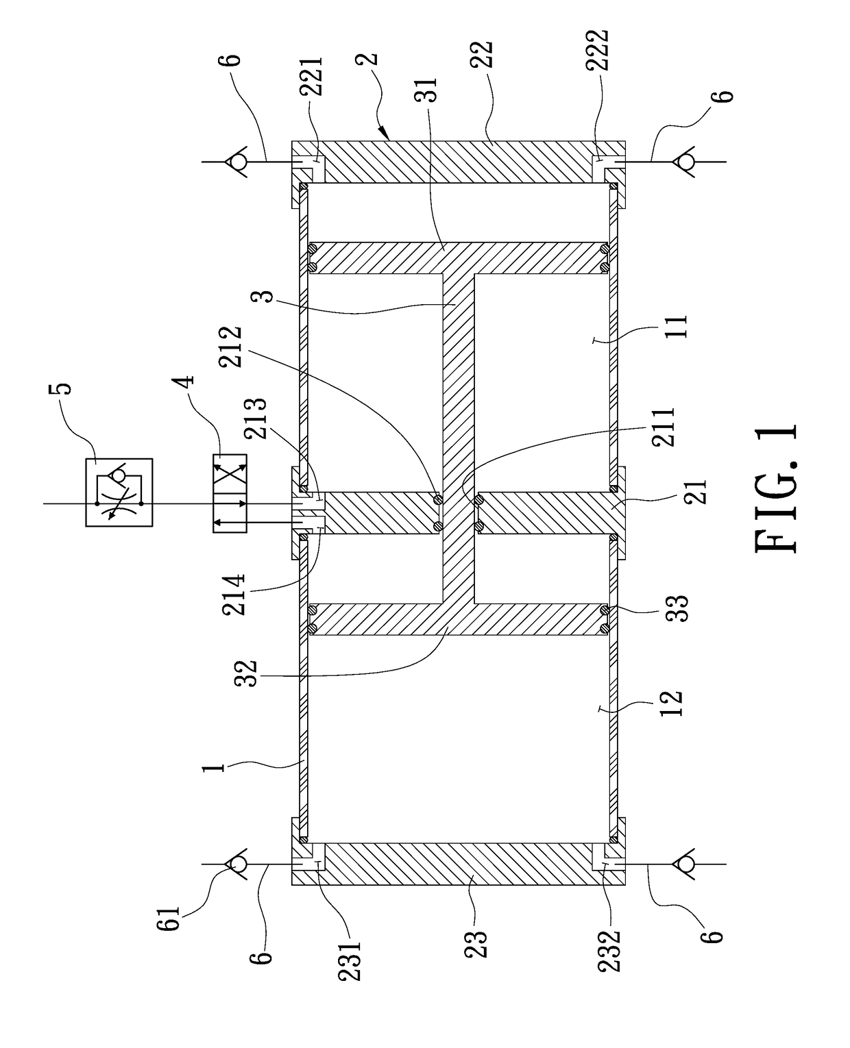
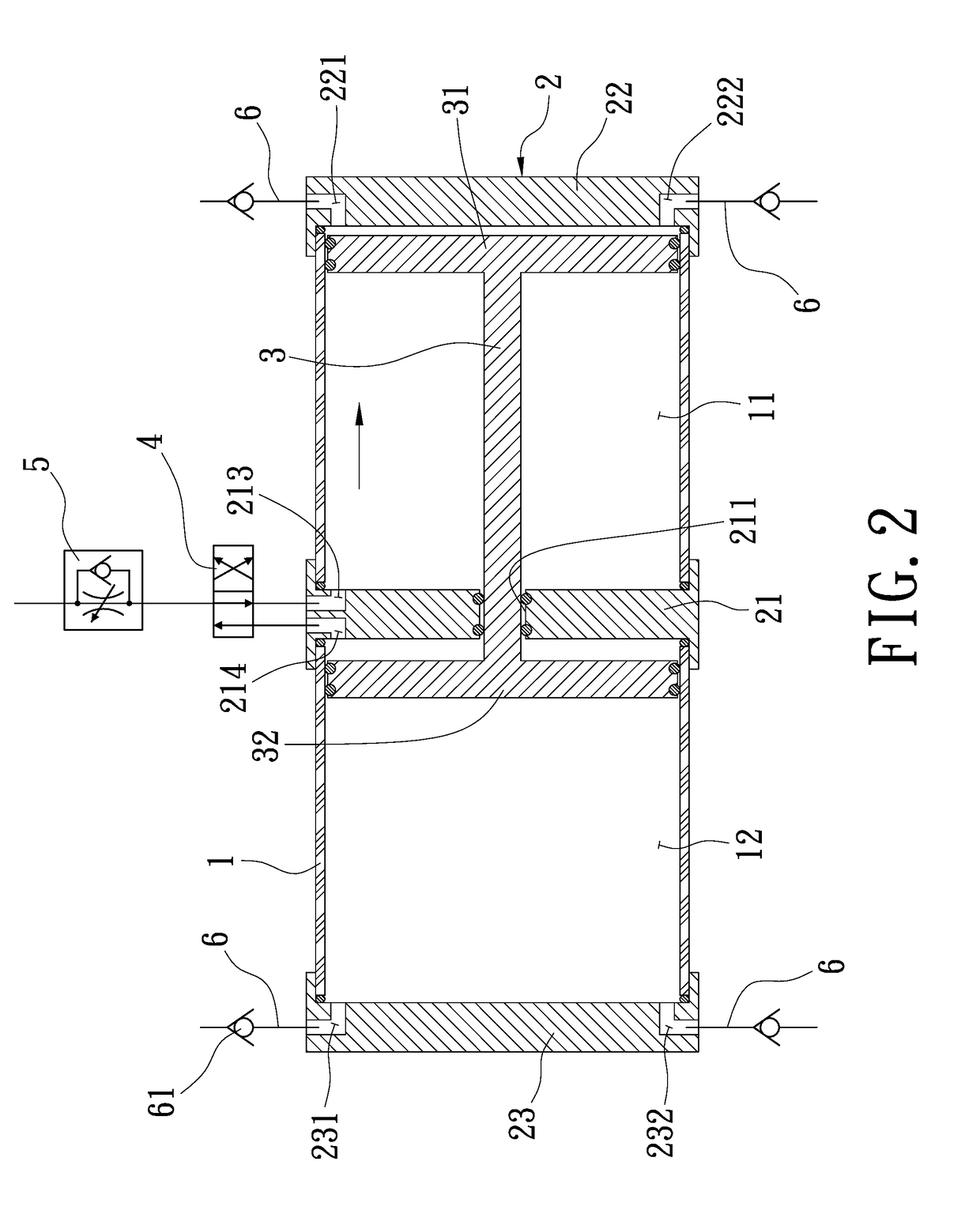
[0018]As showed in FIG. 1, a cross-sectional diagram showing a double-acting pneumatic pump according to the present invention is disclosed. The double-acting pneumatic pump comprises:
[0019]a hollow main body (1);
[0020]at least three partitions (2) for dividing the main body (1) into at least two chambers, wherein one of the at least three partitions (2) is disposed between the at least two chambers; preferentially, the at least two chambers include a first chamber (11) and a second chamber (12), and the at least three partitions (2) include a first partition (21) disposed between the first chamber (11) and the second chamber (12) and bored with a through hole (211) in the middle thereof, a second partition (22) and a third partition (23) respectively disposed as an end wall of the first chamber (11) and the second chamber (12) at the other end ...
PUM
 Abstract
Description
Claims
Application Information