Marine electronic device for presentment of sonar images

a technology of electronic devices and sonar images, applied in the direction of measurement devices, using reradiation, instruments, etc., can solve problems such as affecting user experience and impression of malfunction, and achieve the effect of reducing or preventing lag in the display of the complete sonar imag

Active Publication Date: 2020-02-06
NAVICO HLDG
View PDF0 Cites 1 Cited by
  • Summary
  • Abstract
  • Description
  • Claims
  • Application Information

AI Technical Summary

Benefits of technology

[0006]The marine electronic device may be configured to determine the depth change when the sonar return data is received, such that the fill image may be generated with the generation of the sonar image. This may reduce or prevent lag in display of the complete sonar image. The marine electronic device may be configured to generate the fill image by generating a composite image of a first and second side facing sonar return data. The composite image may include the maximum intensity values, minimum intensity values, or a weighted intensity value for the first and second side facing sonar return data.

Problems solved by technology

These portions of the sonar image may be rendered as blank areas, which may detract from the user experience, or give an impression of a malfunction.

Method used


Image

  • Marine electronic device for presentment of sonar images
  • Marine electronic device for presentment of sonar images
  • Marine electronic device for presentment of sonar images

Examples


example sonar

Images

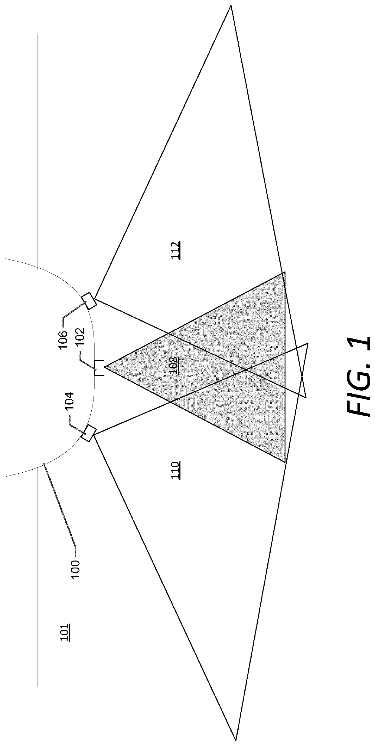
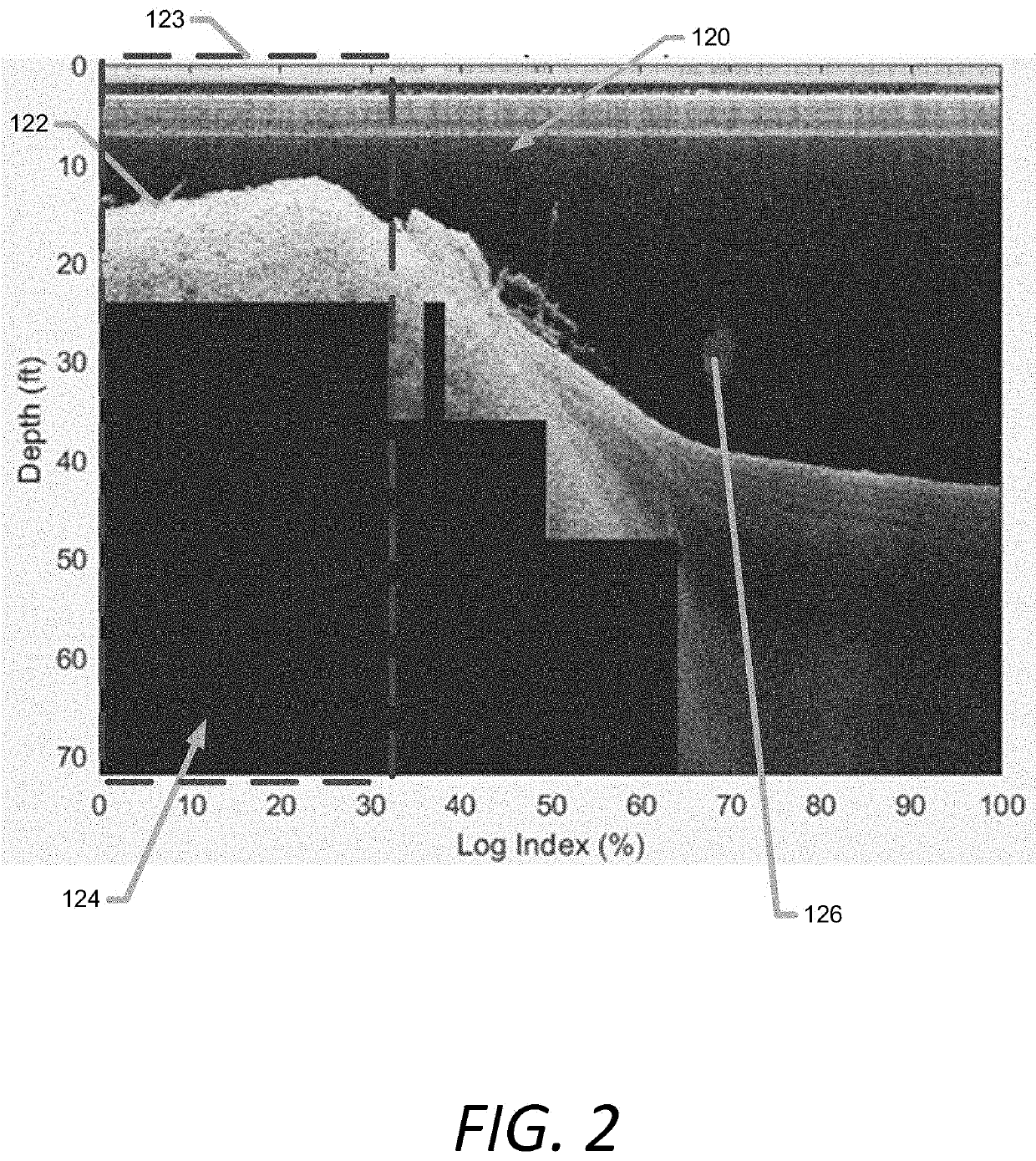
[0031]FIG. 2 illustrates an example down facing sonar image 120. The down facing sonar image 120 may be generated based on a buildup of sonar return data, or sonar slices. Each sonar slice may correspond to a set of sonar returns received at the down facing sonar transducer 102 in response to the emitted sonar beam 108. The sonar image 120 may have a depth range associated with a depth range of the sonar returns. For example, in a left portion 123 of the sonar image (which corresponds to the oldest sonar return data), the displayed sonar imagery is based on a depth range of approximately twenty-five feet. In this regard, in some example embodiments, the depth range associated with the sonar return data may be a function of the bottom depth 122. The sonar return data may include information extending beyond the bottom depth 122 by a predetermined depth. The predetermined depth may be ten feet, fifteen feet, twenty feet, or the like beyond the bottom depth 122. In some example e...

example architecture

[0045]FIG. 9 shows a block diagram of an example computing device, such as an example marine electronic device 405. The marine electronic device 405 may include a number of different modules or components, each of which may comprise any device or means embodied in either hardware, software, or a combination of hardware and software configured to perform one or more corresponding functions. The marine electronic device may also be in communication with a network 402.

[0046]The marine electronic device 405 may also include one or more communications modules configured to communicate with one another in any of a number of different manners including, for example, via a network. In this regard, the communications module may include any of a number of different communication backbones or frameworks including, for example, Ethernet, the NMEA 2000 framework, GPS, cellular, WiFi, or other suitable networks. The network may also support other data sources, including GPS, autopilot, engine dat...


PUM


Abstract

An apparatus configured to generate a first sonar image from first sonar returns corresponding to a first depth range and generate a second sonar image from the first sonar returns and second sonar returns, the second sonar returns corresponding to a second depth range greater than the first depth range of the first sonar returns such that a portion of the second sonar image does not include sonar return data. The portion without sonar return data corresponds to a period of the first sonar returns and depths greater than the maximum depth of the first depth range. The apparatus is configured to generate and display a fill image for the portion of the second sonar image based on at least one set of side facing sonar return data corresponding to the time period associated with the first sonar returns.

Description

FIELD OF THE INVENTION[0001]Embodiments of the present invention relate generally to generating sonar images, and more particularly, to systems and apparatuses for providing improved down sonar images.BACKGROUND OF THE INVENTION[0002]A marine electronic device may be configured to receive marine data from one or more data sources including from sonar transducers. Sonar data may be used to detect features of and / or objects in an underwater environment. In particular, when analyzed, sonar return data may be used to determine depths of a marine environment, detect fish or other waterborne objects, locate wreckage, and / or the like. An operator of a watercraft may use sonar image data, based on the sonar return data, to assist with the navigation of the watercraft and / or to perform other functions. The sonar images utilize sonar data received from one or more transducers on a vessel to provide a “picture” of the underwater environment.BRIEF SUMMARY OF THE INVENTION[0003]A display panel c...

Claims


Application Information

Patent Timeline
Patent Type & Authority Applications(United States)
IPC IPC(8): G01S7/58G01S15/89
CPCG01S7/58G01S15/8902G01S7/6236G01S7/6281
Inventor HORNER, RONALD
Owner NAVICO HLDG
Why Eureka
Try Eureka