Railway switch circuit controller

a switch circuit and switch controller technology, applied in the direction of railway signalling, railway signalling and safety, point operation from vehicles, etc., can solve the problems of requiring frequent maintenance, requiring too much money for maintenance personnel to be cost-effective, and requiring too much money for individual mechanical parts replacemen

Inactive Publication Date: 2000-05-16
ANSALDO STS USA INC
View PDF3 Cites 31 Cited by
  • Summary
  • Abstract
  • Description
  • Claims
  • Application Information

AI Technical Summary

Problems solved by technology

It has been found in the harsh railroad environment that the repetitive cycling between normal and reverse positions of the switch points results in wear and tear on the movable mechanical parts with

Method used


Image

  • Railway switch circuit controller
  • Railway switch circuit controller
  • Railway switch circuit controller

Examples


Embodiment Construction

of the Figures

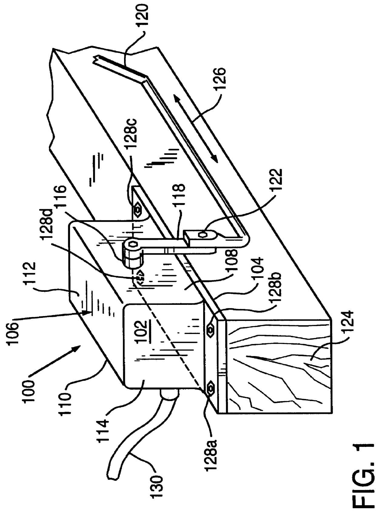
Referring now to the drawings in detail, FIG. 1 shows a top perspective view of a railway switch circuit controller 100 in accordance with a preferred embodiment of the present invention, having a housing 102 with a bottom surface 104, a top surface 106, opposing side surfaces 108, 110, and opposing end surfaces 112, 114. A shaft 116 is rotatably disposed through the side surfaces 108, 110. As is known in the art, a crank arm 118 may be connected to the shaft 116 and a point detector connecting rod 120 may be connected to the crank arm 118 with a connector 122, such as a known clamp assembly, for instance, thereby to partially rotate the shaft 116 when the point detector connecting rod 120 is moved laterally in a direction which is parallel to a railroad tie 124, as shown by an arrow 126.

One skilled in the art will recognize that attaching the connecting rod 120 below the shaft 116, as shown in FIG. 1, will rotate the shaft 116 in a first rotational direction when the ...


PUM


Abstract

A railway switch circuit controller has a housing enclosing a laterally movable platform with a first and second target affixed thereupon. A first and second proximity sensor within the housing is positioned to detect the first and second target, respectively, such that the proximity sensor upon detection of the respective target may provide a signal. The platform is connected to a point detector connecting rod of a railway switch, thereby to be movable relative to the movement of the point detector connecting rod. In a first preferred embodiment, the platform may be cooperatively engaged with a rotational drive shaft that is connected to the point detector connecting rod, thereby to move laterally when the drive shaft is rotated by lateral movement of the rod. In the first preferred embodiment, the first and second proximity sensor may be fixed within the housing and the first and second target may be adjustable laterally within the platform towards and away from the other target, respectively.

Description

1. Field of the InventionThe present invention relates generally to railway switching devices and, more particularly, to a railway switch circuit controller for controlling a circuit associated with the railway switching device.2. Description of the Related ArtRailway turnouts alternatively divert trains from one set of tracks to another set of tracks. A common turnout used in the industry has a switch property which includes: switch points connected to a point detector connecting rod, a switching device or machine that is connected with an operating rod to the point detector connecting rod, a frog to carry the train wheel flanges across opposing rails, and lead rails between the frog and the switch points. In operation, the operating rod transmits the operating force of the switching device to the switch points, thereby causing the switch points to move. The point detector connecting rod follows the movement of the switch points and translates the position of the switch points at a...

Claims


Application Information

Patent Timeline
IPC IPC(8): B61L5/10B61L5/00
CPCB61L5/107
Inventor MCQUISTIAN, KEVIN M.
Owner ANSALDO STS USA INC
Why Eureka
Try Eureka