Medical ventilator triggering and cycling method and mechanism

a technology of triggering and cycling, applied in the field of medical ventilators, can solve the problems of false triggers or cycles, and the need for a greater amount of patient effor

Inactive Publication Date: 2003-09-30
RIC INVESTMENTS LLC
View PDF19 Cites 399 Cited by
  • Summary
  • Abstract
  • Description
  • Claims
  • Application Information

AI Technical Summary

Benefits of technology

According to a further embodiment of the present invention, a plurality of triggering mechanisms are made active during different stages of the expiratory phase of the patient's breathing cycle to increase the ventilator system sensitivity to a patient initiated trigger as the expiratory phase of the breathing cycle progresses.

Problems solved by technology

This one-dimensional, i.e., one parameter, comparison of either pressure, flow, or volume to a trigger threshold is disadvantageous in that it is susceptible to random fluctuations in the monitored parameter, which may result in false triggers or cycles.
However, reducing the ventilator's sensitivity can result in a greater amount of patient effort being needed before a spontaneous patient inspiration or expiration is detected, which is also disadvantageous, because a patient on a ventilator often has a weakened respiratory system to begin with.

Method used


Image

  • Medical ventilator triggering and cycling method and mechanism
  • Medical ventilator triggering and cycling method and mechanism
  • Medical ventilator triggering and cycling method and mechanism

Examples


Embodiment Construction

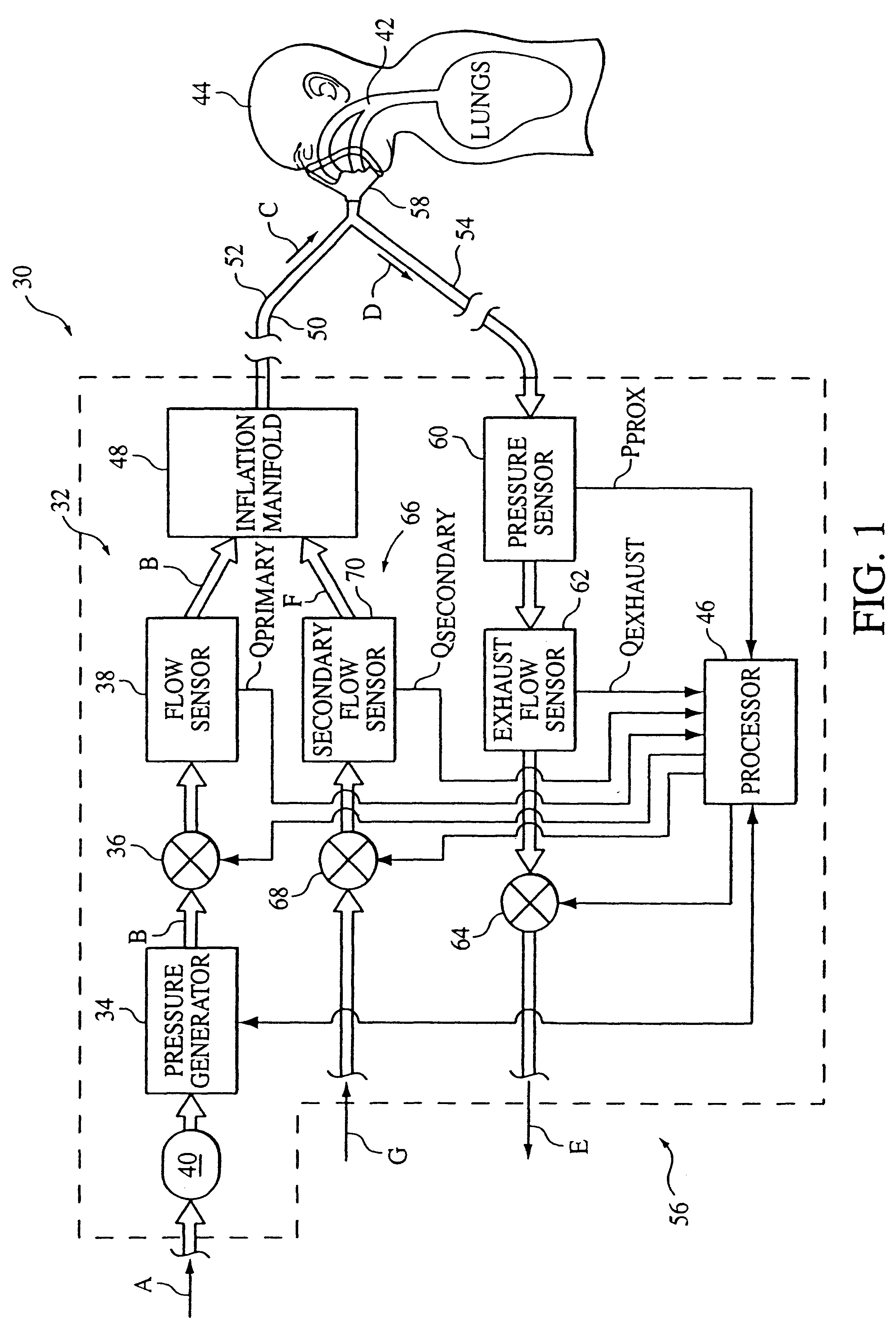
FIG. 1 schematically illustrates an exemplary embodiment of a ventilator system 30 according to the principles of the present invention. Ventilator system 30 is adapted to operate in an invasive mode, where the patient is typically intubated, or in a non-invasive mode, where the patient is not intubated. The basic components in ventilator 30 correspond to those found in a conventional ventilator, such as the Esprit.RTM. Ventilator manufactured by Respironics, Inc. of Pittsburgh, Pa., with the novel aspect of the present invention being the techniques used by the ventilator to trigger and / or cycle, such as utilizing recognition and quantification of physiologic-based concomitant multi-signal patterns, as opposed to a single signal pattern of conventional ventilators, for triggering purposes, cycling purposes, or both.

A. Ventilator System Hardware

Ventilator system 30 includes a primary gas flow delivery system, generally indicated at 32, which includes a pressure generator 34, a press...


PUM


Abstract

A medical ventilator system and method that triggers, cycles, or both based on patient effort, which is determined from cross-correlating patient flow and patient pressure. The medical ventilator is also controlled such that sensitivity to a patient initiated trigger increases as the expiratory phase of the breathing cycle progresses. The present invention also provides adaptive adjustment of cycling criteria to optimize the cycling operation.

Description

1. Field of the InventionThe present invention pertains to a medical ventilator with improved spontaneous triggering and cycling and to an improved method of triggering and cycling such a ventilator. In particular, the present invention pertains to a ventilator with one or more of the following features: (1) sensitivity to a patient initiated trigger that increases as the expiratory phase of the breathing cycle progresses, (2) adaptive adjustment of cycling criteria to optimize the cycling operation, and (3) triggering, cycling, or both based on patient effort, which is determined from cross-correlating multiple patient parameters.2. Description of the Related ArtIt is known to utilize a conventional ventilator or pressure support device to deliver a fluid, such as oxygen, air or other oxygen or breathing gas mixture, to an airway of patient to augment or substitute the patient's own ventilatory effort. It is further known to operate a conventional ventilator in a variety of modes t...

Claims


Application Information

Patent Timeline
Patent Type & Authority Patents(United States)
IPC IPC(8): A61M16/00A61M16/10A61M16/12A61M16/20
CPCA61M16/00A61M16/0069A61M16/125A61M16/205A61M2016/0021A61M2016/0039A61M2016/0042A61M2205/15A61M2016/0027A61M16/0858A61M16/026A61M16/0051A61M16/0833
Inventor JAFARI, MEHDI M.KIMM, GARDNER J.MCGUIGAN, KARRIE
Owner RIC INVESTMENTS LLC
Why Eureka
Try Eureka