Multipolar circuit-protection assembly for a collector rail system

Inactive Publication Date: 2005-03-08
BRUCHMANN KLAUS
View PDF14 Cites 56 Cited by
  • Summary
  • Abstract
  • Description
  • Claims
  • Application Information

AI Technical Summary

Benefits of technology

Accordingly, one object of the invention is to provide a multipole fused switch arrangement which

Problems solved by technology

Since such fused switch arrangements are also operated by those not skilled in the art, it has frequently been found

Method used


Image

  • Multipolar circuit-protection assembly for a collector rail system
  • Multipolar circuit-protection assembly for a collector rail system
  • Multipolar circuit-protection assembly for a collector rail system

Examples


Embodiment Construction

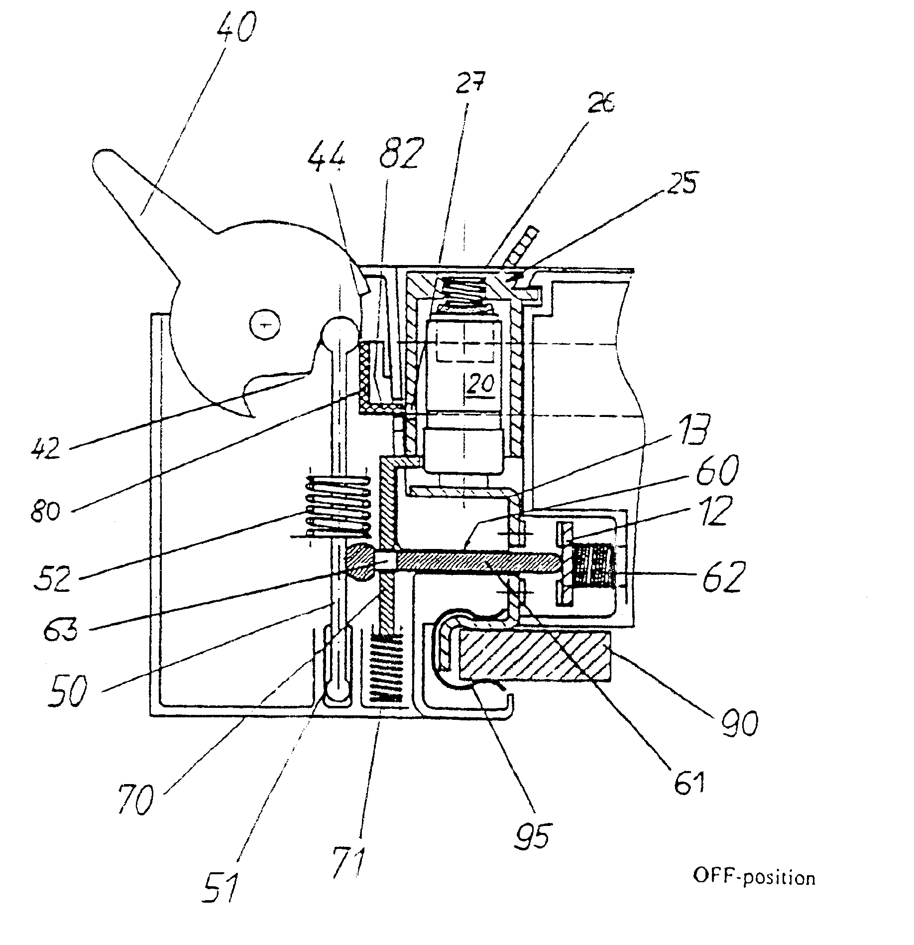
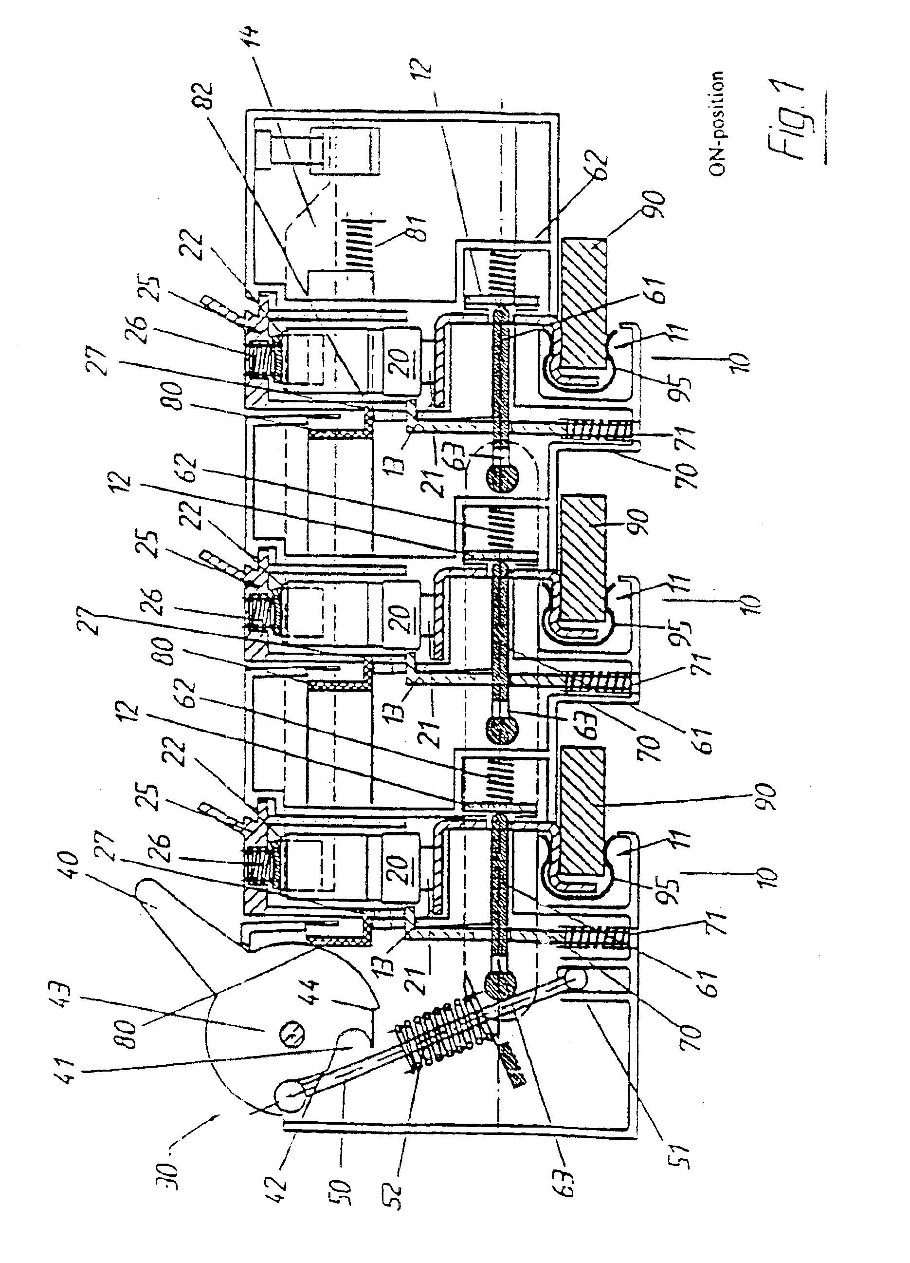
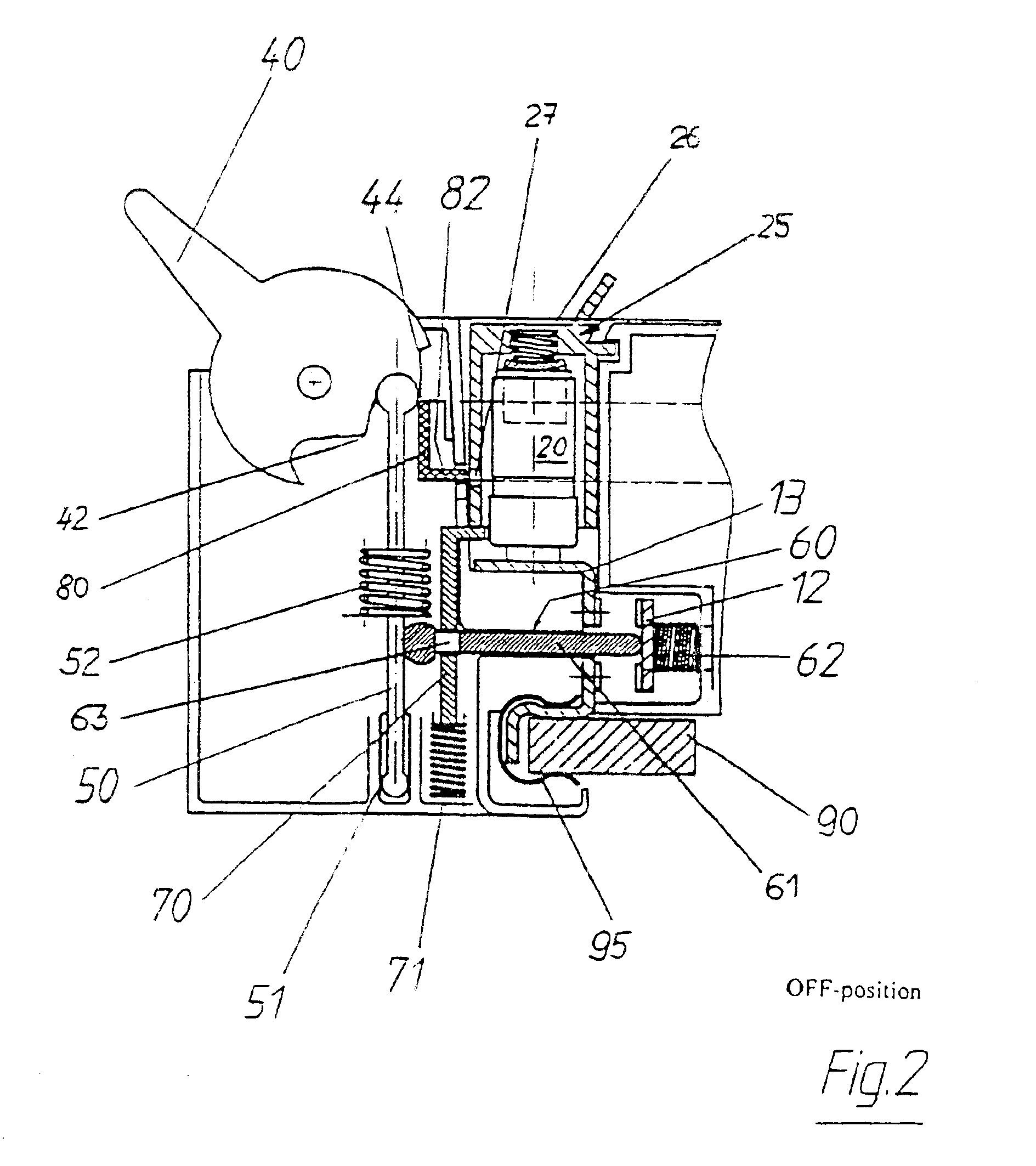
FIG. 1 shows a fused switch arrangement having three fused switch units 10, into each of which a fuse plug 25 with a fuse link 20 is inserted.

Each fused switch unit 10 is mounted on a busbar 90 by means of a surrounding spring 95.

The switching and blocking apparatus according to the invention comprises, in the embodiment shown in FIG. 1, a switching lever 40, a spring-loaded switching rod 50, an operating apparatus 60 which in each case comprises one pushrod 61 per fused switch unit 10, a spring-loaded blocking apparatus 70, and a likewise spring-loaded locking apparatus 80. The spring 52 of the switching rod 50 has a considerably greater spring constant than the springs 62 in the operating apparatus and the springs 81 in the locking apparatus, which have approximately the same spring constants. The springs 71 in the blocking apparatus 70 have the lowest spring constant in the switching and blocking apparatus.

When the fused switch arrangement is in the working position shown in FIG....


PUM


Abstract

The invention relates to a multipole fused switch arrangement for busbar systems having at least two fused switch units (10) which each holds a fuse link (20), with the fused switch units (10) having a mounting and contact apparatus (11) for a busbar, and having a switching apparatus for closing and interrupting the circuit of all the switched fuse units, with the fused switch arrangement comprising a combined switching and blocking apparatus (30), having a switching lever (40), an operating arrangement (60), a blocking apparatus (70) for each fused switch unit (10), and a locking apparatus (80).

Description

TECHNICAL FIELDThe invention relates to a multipole fused switch arrangement for busbar systems having at least two fused switch units which each holds a fuse link, with the fused switch units having a mounting and contact apparatus for a busbar, and having a switching apparatus for closing and interrupting the circuit of all the switched fuse units.BACKGROUND OF THE INVENTIONSuch fused switch arrangements are used in particular for protecting three-phase circuits, in which case three-pole fused switch arrangements are required.Since such fused switch arrangements are also operated by those not skilled in the art, it has frequently been found to be a problem that incorrect operations even on the fused switch arrangement have led to damage to the appliances.SUMMARY OF THE INVENTIONAccordingly, one object of the invention is to provide a multipole fused switch arrangement which is simple to operate and which minimizes the risk of incorrect operations by untrained personnel.The object ...

Claims


Application Information

Patent Timeline
IPC IPC(8): H01H9/10H01H9/00H01H19/635H01H19/00
CPCH01H19/635H01H9/104H01H1/20
Inventor BRUCHMANN, KLAUS
Owner BRUCHMANN KLAUS
Why Eureka
Try Eureka