Ink-jet printer

Inactive Publication Date: 2006-01-03
NK WORKS CO LTD
View PDF7 Cites 27 Cited by
  • Summary
  • Abstract
  • Description
  • Claims
  • Application Information

AI Technical Summary

Benefits of technology

[0006]An object of the present invention is to provide an ink-jet printer capable of ensuring flatness of a printing medium and at the same time rest

Problems solved by technology

When the suction fan drives in this condition, a large amount of air flows into the holes that remain open.
Therefore, there is a problem that, when such a printer performs printing onto the vicinity of the leading edge of the paper, airflow g

Method used


Image

  • Ink-jet printer
  • Ink-jet printer
  • Ink-jet printer

Examples


Embodiment Construction

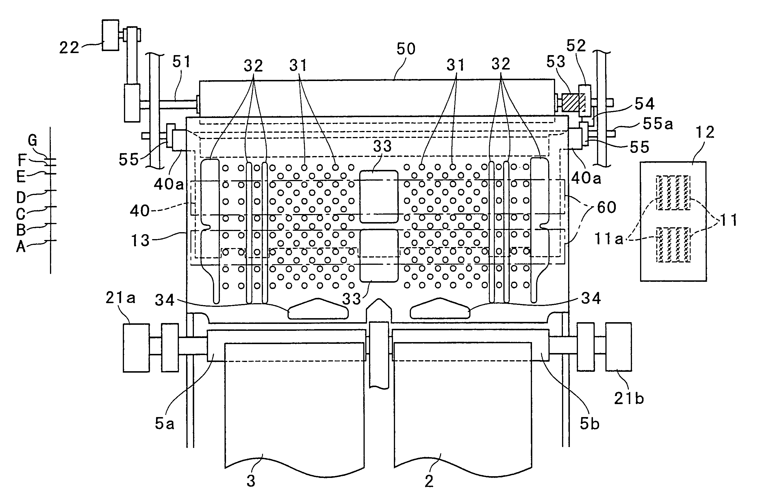
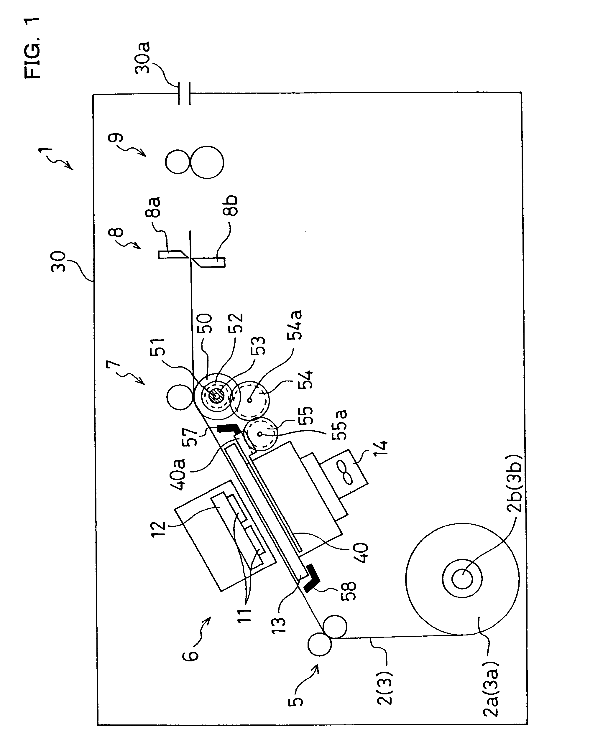
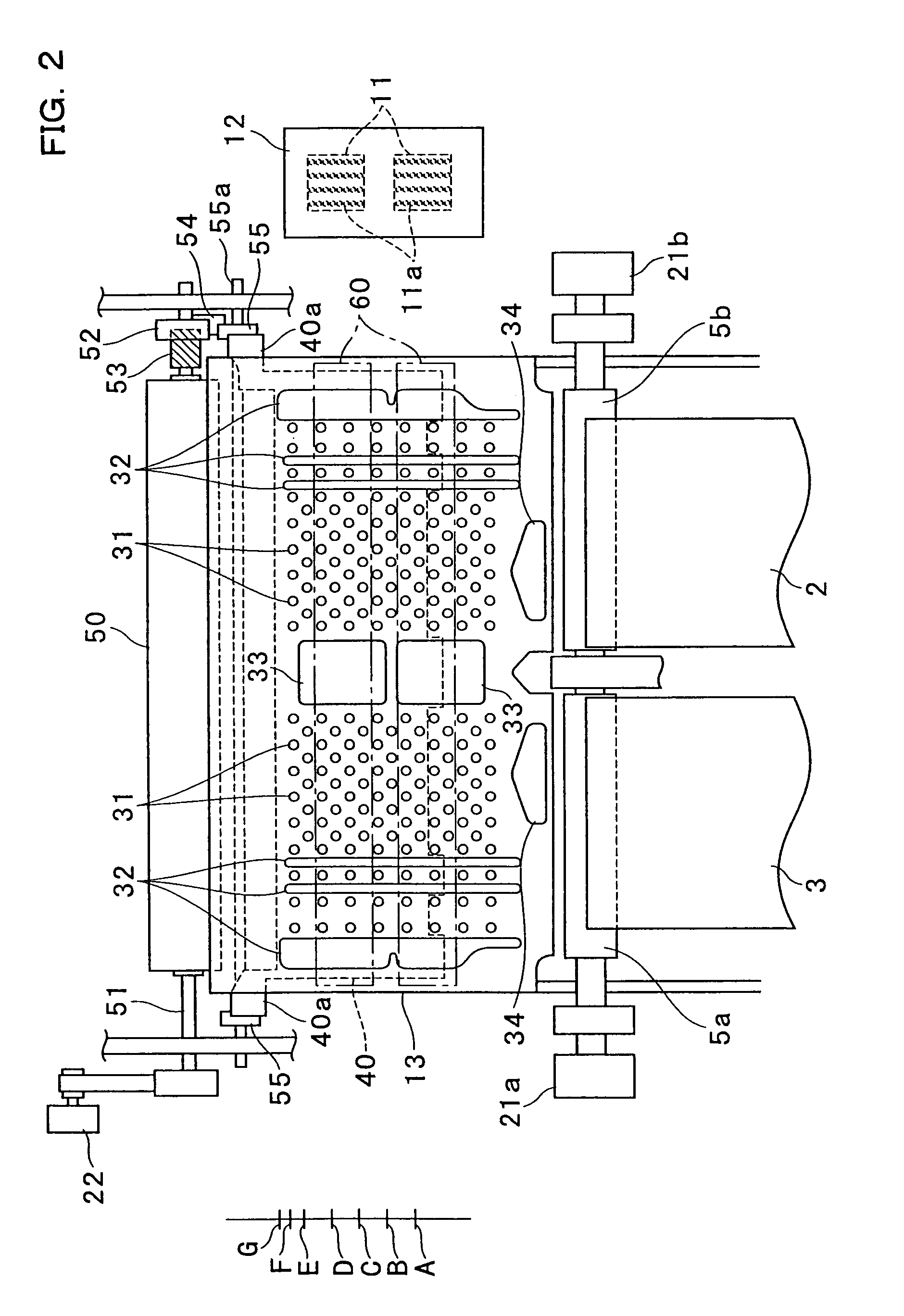
[0015]An ink-jet printer 1 illustrated in FIG. 1 has a substantially rectangular parallelepiped casing 30. The casing 30 includes therein a conveyance roller unit 5, an ink-jet printing unit 6, a press roller unit 7, a cutting unit 8, and a discharge roller unit 9 in this order from upstream in a paper conveyance direction. In the casing 30, additionally, two roll portions 2a and 3a each formed by rolling a long paper 2 or 3 as a printing medium are arranged adjacently to each other in a horizontal direction, i.e. a direction perpendicular to the drawing sheet of FIG. 1, with a predetermined distance therebetween. The roll portions 2a and 3a are supported on drums 2b and 3b, respectively, so as to rotate around their axes. The conveyance roller unit 5, the press roller unit 7, and the discharge roller unit 9 constitute a conveyance mechanism that conveys the papers 2 and 3. A controller (not illustrated) disposed within the casing 30 controls an operation of each part of the ink-jet...


PUM


Abstract

Many holes are formed in a platen that is so disposed as to confront a printing head. A suction fan disposed under the platen generates suction force through the holes formed in the platen to thereby bring a paper into close contact with a surface of the platen. On a back surface of the platen, disposed is an airflow restriction plate formed with openings that correspond to a part of the holes in the platen. Before a leading edge of the paper arrives at the platen, the airflow restriction plate closes the holes. In association with a conveyance of the paper, the airflow restriction plate moves in a paper conveyance direction on the back surface of the platen and, at the same time, opens the closed holes sequentially from upstream in the paper conveyance direction. This can restrict inflow of air into the holes located downstream, in the paper conveyance direction, of the leading edge of the paper.

Description

BACKGROUND OF THE INVENTION[0001]1. Field of the Invention[0002]The present invention relates to an ink-jet printer that ejects ink onto a printing medium to perform printing.[0003]2. Description of Related Art[0004]Some ink-jet printers perform printing by ejecting ink onto a paper as a printing medium from a printing head that reciprocates perpendicularly to a paper conveyance direction. It is important, from the viewpoint of printing quality, to ensure flatness of the paper in a print region confronting the printing head. Thus, particularly when a long paper is used as the printing medium, there may be adopted an approach in which many holes are formed in a platen that supports the paper in the print region and a suction fan disposed under the platen generates suction force through the holes to thereby bring the paper into close contact with a surface of the platen. The holes formed in the platen are, in general, arranged on an entire surface of the platen in a substantially unif...

Claims


Application Information

Patent Timeline
IPC IPC(8): B41J11/02B41J2/01B41J11/00B41J11/06B41J15/18
CPCB41J11/0065B41J11/0085B41J15/18B41J11/06B41J11/0095
Inventor TSUJI, MASAAKI
Owner NK WORKS CO LTD
Why Eureka
Try Eureka