Circuit breaker comprising a control assembly and interrupting chamber and method of assembly

a technology of circuit breakers and control assemblies, applied in the field of circuit breakers, can solve the problems of inacceptable modification of the position of the moving contact, particularly difficult to achieve both fits,

Inactive Publication Date: 2006-01-17
ALSTOM TECH LTD
View PDF3 Cites 1 Cited by
  • Summary
  • Abstract
  • Description
  • Claims
  • Application Information

AI Technical Summary

Benefits of technology

[0012]In this context, an object of the invention is to provide a circuit-breaker that makes it possible to remedy the above-mentioned drawbacks.
[0015]Finally, an object of the invention is to provide such a circuit-breaker whose synchronization assembly has small clearances when in operation, while offering satisfactory flexibility, in particular as regards assembling it and disassembling it.
[0034]an “optimum” one of said radial marks is identified that corresponds to a free insertion position in which the adapter can be inserted freely into the gap;

Problems solved by technology

It is easy to understand that achieving both fits can be particularly difficult.
This difficulty is due in particular to the manufacturing tolerances for the various elements of the circuit-breaker.
Turning the shaft of the interrupting chamber through an angle that can be as great as several degrees generally results in an inacceptable modification in the position of the moving contact.

Method used


Image

  • Circuit breaker comprising a control assembly and interrupting chamber and method of assembly
  • Circuit breaker comprising a control assembly and interrupting chamber and method of assembly
  • Circuit breaker comprising a control assembly and interrupting chamber and method of assembly

Examples


Embodiment Construction

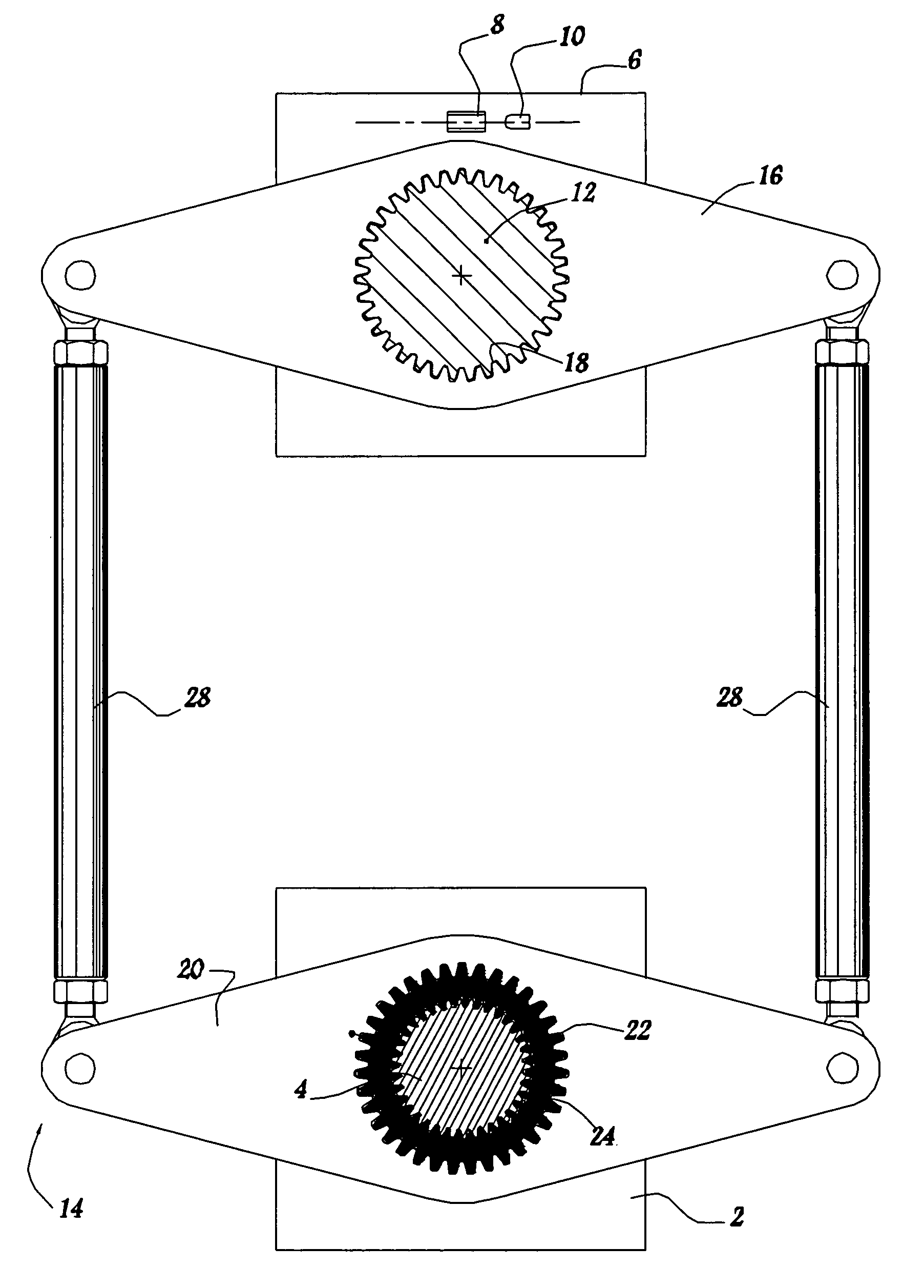
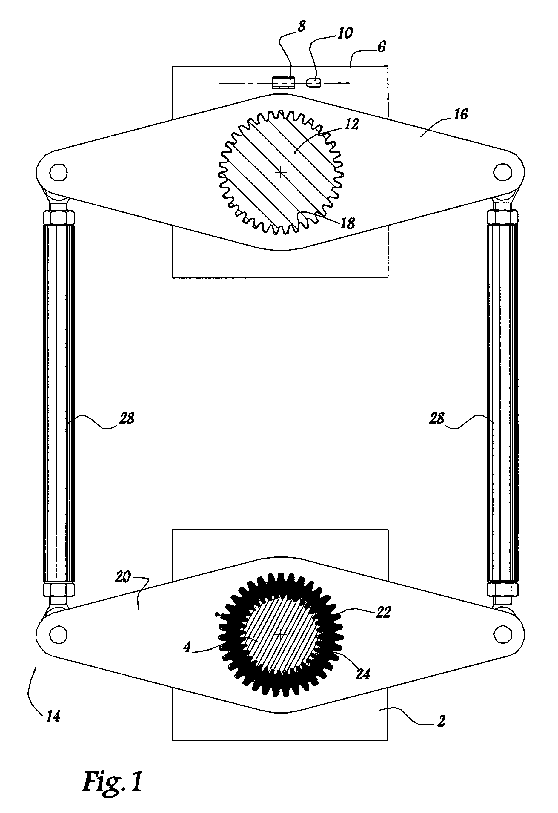
[0051]The circuit-breaker shown in FIG. 1 includes a control assembly which is shown diagrammatically in the form of a block 2. The control assembly 2, which, in known manner, is capable of storing mechanical energy, in particular by means of springs (not shown) is provided with a splined control shaft 4.

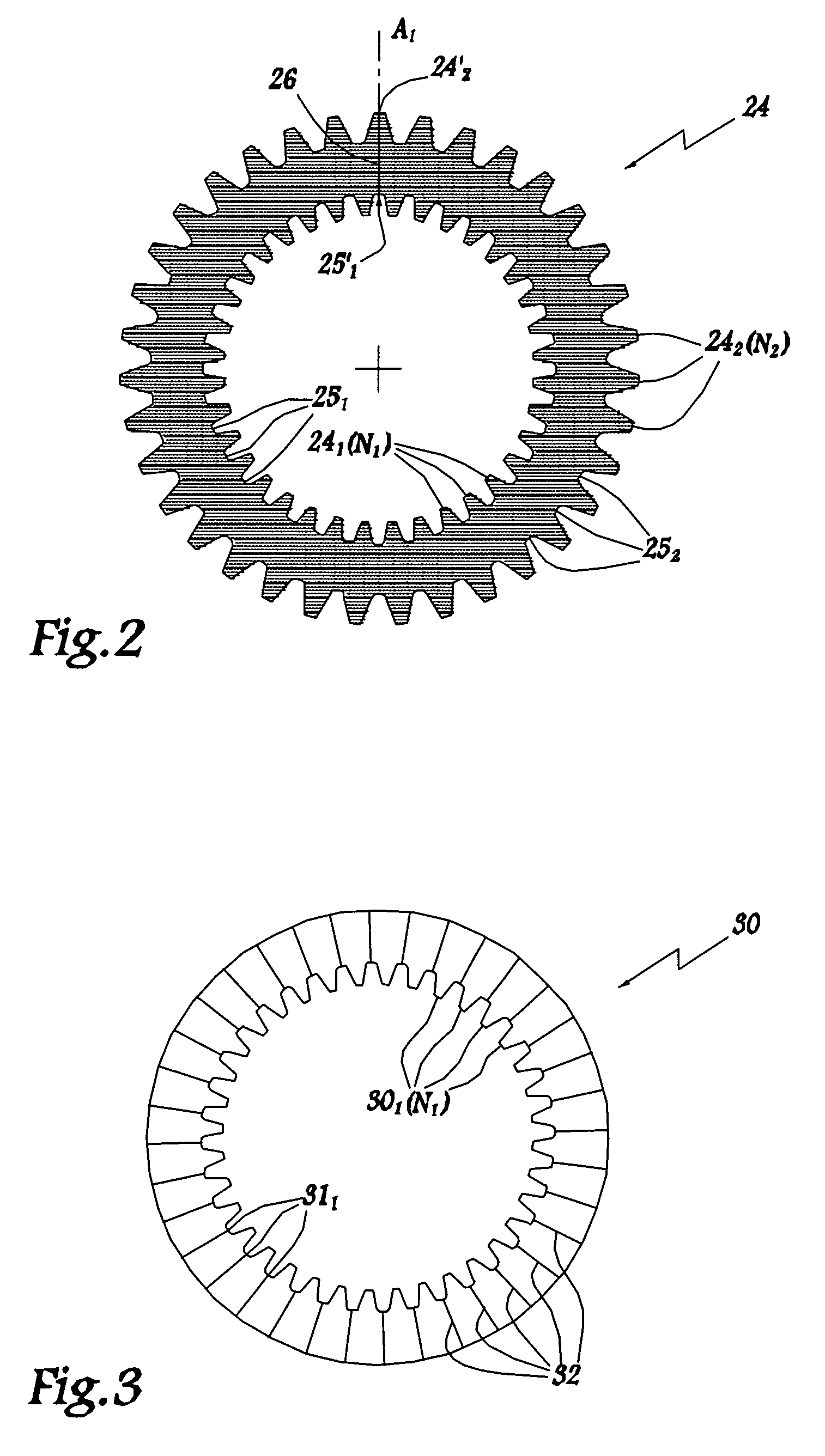
[0052]In the context of the present invention, the term “splined” is used to mean that the mechanical member in question is provided with meshing elements, which may, in particular, be teeth or splines. Below, it is assumed that the various mechanical members are provided with splines that form said meshing elements.

[0053]The circuit-breaker also includes an interrupting chamber, which is also shown diagrammatically in the form of a block 6. In conventional manner, the interrupting chamber 6 has fixed and moving contacts, respectively 8 and 10, both of which are also shown diagrammatically.

[0054]A splined interrupting chamber shaft 12 is also provided which, by turning, moves the mo...


PUM


Abstract

A circuit breaker including a control assembly having a driving and a driven splined shafts and a pair of arcing contacts movable by the control assembly. A synchronization assembly is provided for synchronizing the two splined shafts and includes two levers each of which is provided with a splined ring that co-operates with one of the splined shafts. One of the splined rings has a number of meshing elements which is different than a number of meshing elements on the splined shaft with which it co-operates and an adapter is seated between the one of the splined rings and the splined shaft with which it co-operates.

Description

BACKGROUND OF THE INVENTION[0001]1. Field of the Invention[0002]The present invention relates to a circuit-breaker comprising a control assembly and an interrupting chamber. It also relates to a method of assembling such a circuit-breaker, and to an auxiliary member for performing such assembly.[0003]2. Description of the Related Art[0004]Conventionally, such a circuit-breaker comprises a control assembly that is associated with an interrupting chamber. The chamber contains a pair of arcing contacts, at least one of which can be moved under the action of the control assembly. The moving contact can thus be moved between two distinct positions, corresponding respectively to opening and to closure of the circuit-breaker.[0005]The above-mentioned control assembly is suitable for storing mechanical energy, in particular by means of the presence of springs. It is also provided with a splined control shaft that can be caused to turn by releasing the mechanical energy stored in the control...

Claims


Application Information

Patent Timeline
Patent Type & Authority Patents(United States)
IPC IPC(8): H01H3/40F16D3/18H01H33/42F16D1/12
CPCH01H33/42F16D1/12
Inventor LEDRU, ROGERGRIESHABER, WOLFGANG
Owner ALSTOM TECH LTD
Why Eureka
Try Eureka