Method and apparatus for x-ray mammography imaging

a mammography and x-ray technology, applied in mammography, medical science, diagnostics, etc., can solve the problems of painful skin tearing, ineffective horizontal force and vector to push the compressed posterior breast, etc., to reduce the heel effect of longer and more incident x-rays, shorten the x-ray distance, and reduce the heel

Inactive Publication Date: 2006-02-14
ADVANTAGE IMAGING
View PDF3 Cites 32 Cited by
  • Summary
  • Abstract
  • Description
  • Claims
  • Application Information

AI Technical Summary

Benefits of technology

[0018]In accordance with a preferred embodiment, there is provided an improved method and apparatus for compressing substantially the posterior breast at a location adjacent the chest wall and to stabilize this tissue while in a compressed state without pushing of the posterior breast tissue back into the chest wall and from the imaging area, and then to compress the middle and anterior tissue with an inclined portion providing a substantial compression of the middle and anterior breast over a wide range of sizes, shapes and densities of breasts without an interfering shadow in the imaging area and without pushing the posterior tissue back into the chest wall and from the imaging area. Preferably, this is achieved by a patient and operator user-friendly method with less discomfiture to the patient. By way of an example only, the initial compression of the posterior breast tissue at the chest wall between the paddle and bucky is achieved by the paddle traveling downwardly through about six centimeters without the patient feeling any significant discomfiture; and then rather than displacing the paddle vertically relative to the bucky where the patient feels significant discomfiture and / or pain, the posterior ends of the bucky and paddle remain at this 6 centimeter displacement and an inclined portion on the paddle or bucky is swung to compress the middle and anterior breast portions.

Problems solved by technology

Because of the substantial, initial compression of the posterior breast tissue, this horizontal force and vector is not effective to push the compressed posterior breast tissue laterally into the chest wall and from the imaging volume.
Because the skin covering the posterior breast tissue at the chest wall will have already been displaced and be taut, the additional downward travel of the posterior end for another 2 or 3 centimeters results in discomfiture and may result in painful skin tearing, as above described.

Method used


Image

  • Method and apparatus for x-ray mammography imaging
  • Method and apparatus for x-ray mammography imaging
  • Method and apparatus for x-ray mammography imaging

Examples


Embodiment Construction

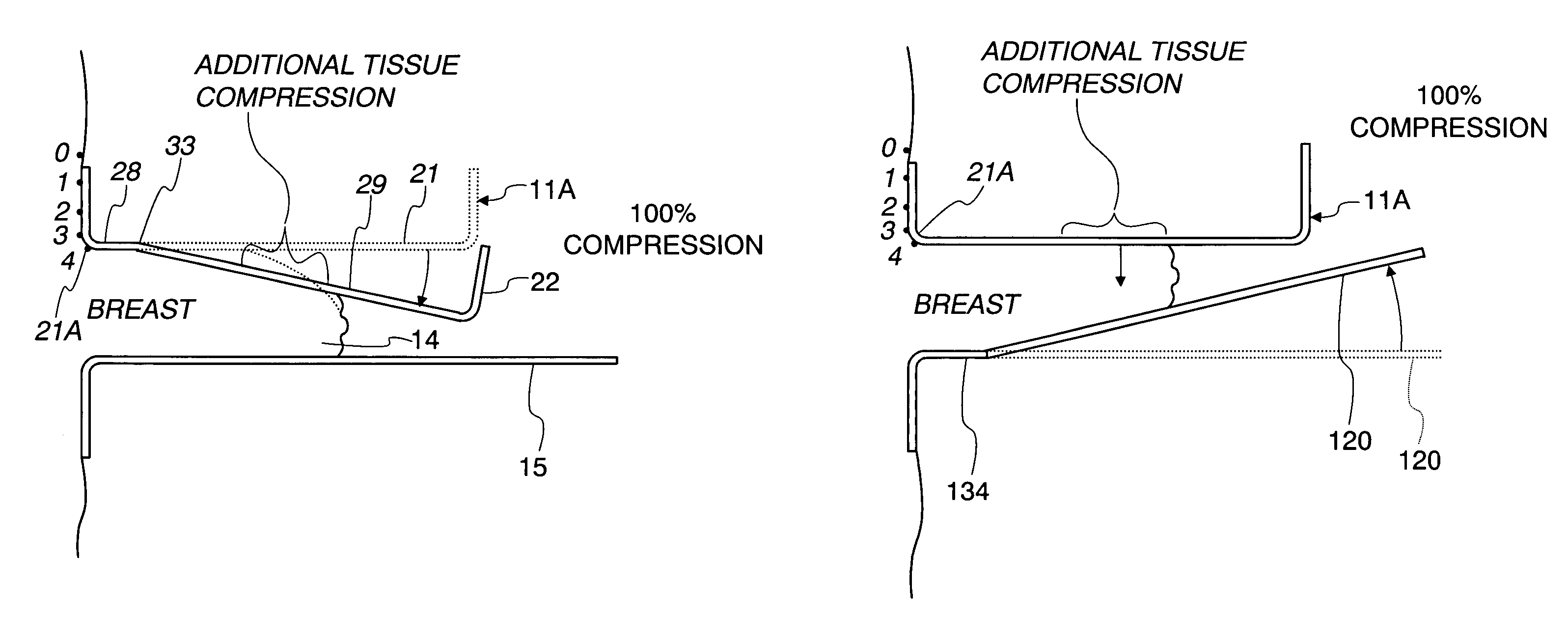
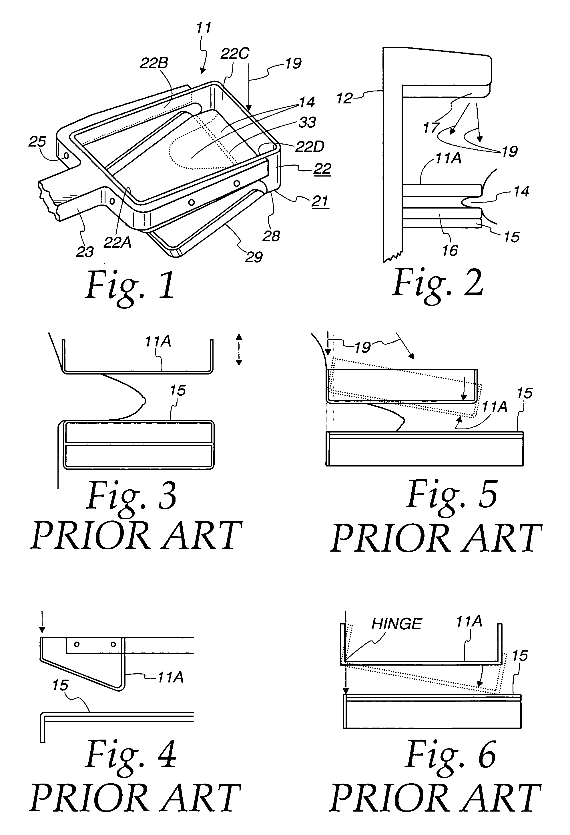
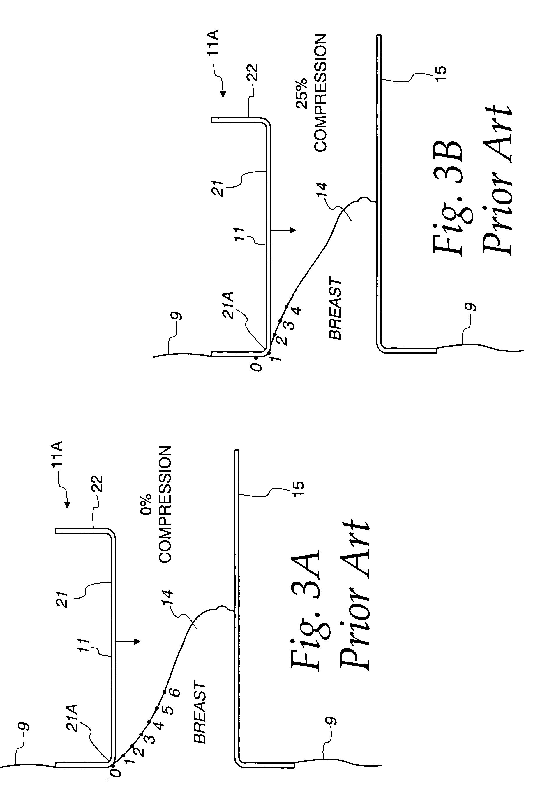
[0074]Referring to FIG. 1 that shows a breast compression device or paddle 11 for use in a common type of mammography imaging machine 12 (FIG. 2) with which the invention paddle can be utilized. In the procedure for taking a mammography image, the patient's breast is supported on a support plate or bucky 15 holding an X-ray detector such as a film in a film cassette 16. An X-ray source 17 provides the X-ray s to take an image of the breast. The X-ray beam indicated by arrow lines 19 covers the X-ray film 16. One edge of X-ray beam extends essentially parallel to the patient's chest and it and other incident X-ray s encompass the breast and the area of film 16. A compression paddle 11A is positioned adjacent the chest wall and over the breast 14 preparatory to compressing the breast for taking an X-ray image of the breast.

[0075]The compression paddle 11 shown in FIG. 1 is preferably constructed of a radiolucent or X-ray transparent material such as PETG (polyethylene terephtalate gly...


PUM


Abstract

A mammographic method and apparatus are provided for obtaining improved compression of posterior, middle and anterior breast tissue without pushing posterior breast tissue from the imaging volume and with less discomfiture to the patient. An initial compression of the posterior tissue is achieved by vertical, relative displacement of the paddle relative to the bucky assembly to compress the posterior breast tissue therebetween. Less patient discomfiture is achieved by using an inclined compression surface on the paddle or bucky assembly to compress the anterior and middle breast sufficiently for good X-ray imaging without further displacement of the skin adjacent the chest wall. A horizontal force component inclined force will not push the posterior compressed breast tissue from the imaging area. Herein a paddle may have a posterior breast section and have a flexed section which is biased to engage and conform to the breast shape. The flexed section may be releasably held by a lock and then released to apply compression forces to the middle and anterior breast. The flexed section is guided to remain level and to uniformly compress breasts which are not centered thereunder and without binding. The buckey assembly may have a hinged inclined section to compress the middle and anterior portions of the breast. The entire bucky assembly may be hinged to raise the image detector thereon and thereby lessen the heel effect. Alternatively, the bucky cover may be hinged to swing upwardly into an inclined position to compress the middle and anterior breast portions while the image detector is not.

Description

[0001]This application claims the benefit of U.S. Provisional Patent Application No. 60 / 451,777; Filed: Mar. 4, 2003 and U.S. Provisional Patent Application No. 60 / 511,593; Filed: Oct. 15, 2003; entitled “Mammography System.”FIELD OF THE INVENTION[0002]This invention relates to a method and apparatus for use in breast mammography and also to a compression paddle and a bucky therefor.BACKGROUND OF THE INVENTION[0003]In mammography systems the most commonly used compression device includes a compression paddle which is parallel to an image detector on a bucky and the paddle is moved vertically relative to the bucky with a patient's breast therebetween to compress the breast. The compressed breast is then exposed to x-rays to obtain a mammography image on a film or on a digital detector such as a semi-conductor detector. Compression of the breast enables better x-ray imaging because the breast is thinner, the breast tissue is spread, there are fewer superimposed layers of tissue in the...

Claims


Application Information

Patent Timeline
Patent Type & Authority Patents(United States)
IPC IPC(8): A61B6/04
CPCA61B6/502A61B6/0414
Inventor LIVINGSTON, TROY
Owner ADVANTAGE IMAGING
Why Eureka
Try Eureka