System and method for connecting geographically distributed virtual local area networks

a virtual local area network and network connection technology, applied in the field of virtual local area networks, can solve the problems etc., and achieves the effect of reducing the flexibility of transmissions over the wan and adding to the overhead of data transfer over the wan

Active Publication Date: 2006-08-08
AVAYA INC +1
View PDF3 Cites 53 Cited by
  • Summary
  • Abstract
  • Description
  • Claims
  • Application Information

AI Technical Summary

Benefits of technology

[0004]The present invention comprises a unit that allows VLANs to extend over wide area networks. In one embodiment, the VLAN frames are bridged and sent to another VLAN segment across the WAN. This bridgin...

Problems solved by technology

First, the bridging adds to the overhead of the data transfer over the WAN.
Addit...

Method used


Image

  • System and method for connecting geographically distributed virtual local area networks
  • System and method for connecting geographically distributed virtual local area networks
  • System and method for connecting geographically distributed virtual local area networks

Examples


Embodiment Construction

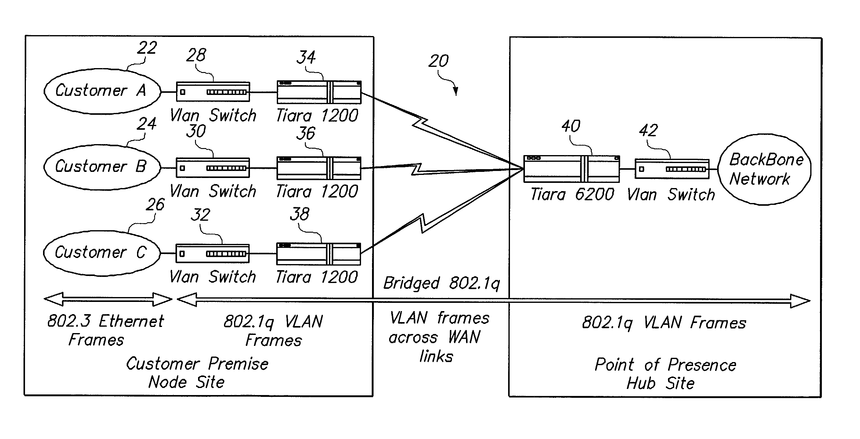
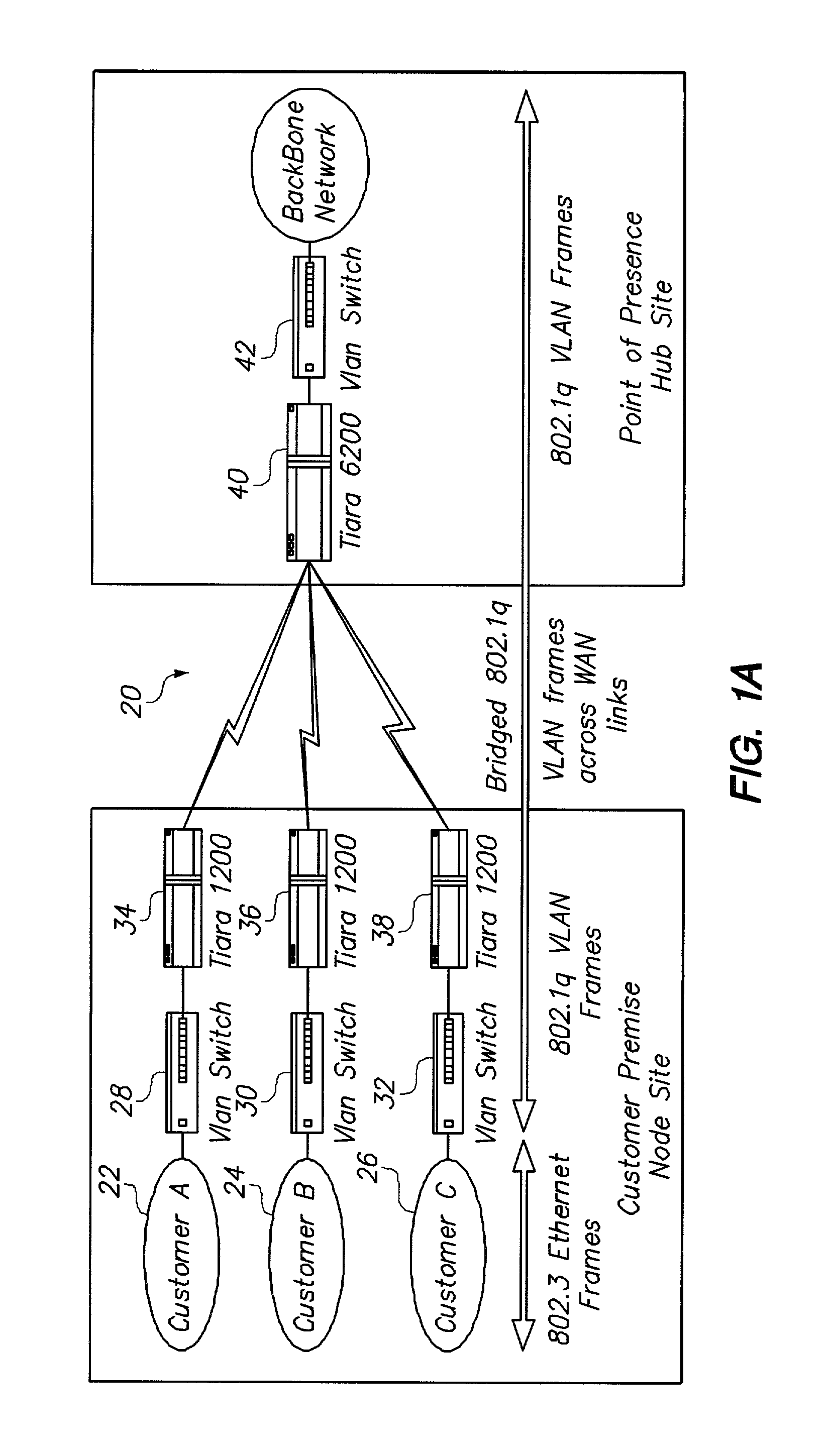
[0036]FIG. 1A is a diagram that illustrates one embodiment of the system of the present invention. The system 20 includes a number of customer networks 22, 24 and 26. In this embodiment, the customer networks are associated with the VLAN switches 28, 30 and 32. The VLAN switching changes the normal Ethernet frames into 802.1q VLAN frames. These 802.1q VLAN frames are sent to the units 34, 36 and 38. These units append the Point to Point Protocol (PPP) header, or other protocol header, and bridge the 802.1q frames to the unit 40. The unit 40 strips the PPP header, or other protocol header and other overhead from the frames and sends the stripped 802.1q VLAN frames off to other elements, such as the VLAN switch 42.

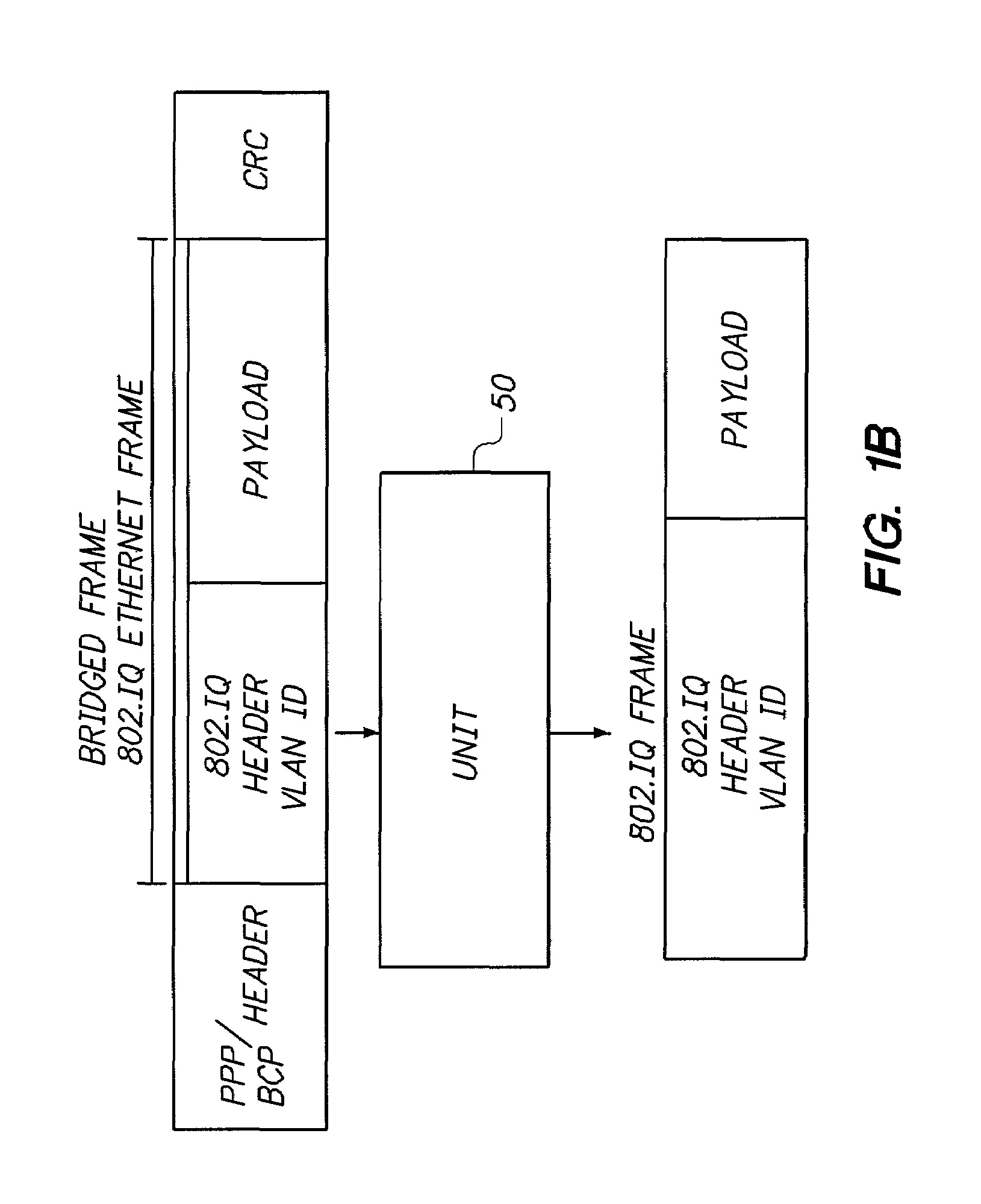
[0037]FIG. 1B illustrates the stripping operation of the unit 40 shown in FIG. 1. As shown in FIG. 1B, the unit 50 receives a bridge frame, containing within it an 802.1q Ethernet frame. The unit 50 strips the 802.1q frame and transmits it to additional network elements. Suc...


PUM


Abstract

A VLAN tagging unit associated with a WAN is used to add VLAN tags based upon logical interfaces. In one example, data received across the logical interface is tagged with an associated VLAN ID by the unit. In another embodiment, flow-based VLAN tagging is done in which in addition to the logical interface other indications are used in the VLAN tagging.

Description

RELATED APPLICATION[0001]This application claims priority under 35 U.S.C. § 119(e) to U.S. Provisional Patent Application No. 60 / 227,862, filed Aug. 24, 2000.BACKGROUND OF THE INVENTION[0002]The present invention relates to Virtual Local Area Networks (VLANs). VLANs allow multiple community groups to coexist within one bridge. A bridging community is identified by its VLAN ID. As described in IEEE 802.1q standard, if a system that supports VLANs receives a frame from the LAN, the frame will only be admitted to a LAN which belongs to the same community. A disadvantage of the VLAN standard 802.1q is that it does not support interactions over Wide Area Networks (WANs). It is desired to have a VLAN supported over a wide area network because it would allow the logical grouping of resources between a customer premise equipment (CPE) location and a point of presence (POP) location.[0003]For this reason, it is desired to have systems and apparatus that support VLANs over wide area networks....

Claims


Application Information

Patent Timeline
IPC IPC(8): H04L12/50H04L12/46H04L12/56
CPCH04L12/4645H04L47/2441H04L47/10
Inventor ATHREYA, ANAND S.BRAILAS, NICHOLAS M.NATARAJAN, ALAMPOONDI E.BHAU, NEHAL
Owner AVAYA INC
Why Eureka
Try Eureka