Bumper assembly for a vehicle and corresponding vehicle comprising said bumper assembly

a bumper assembly and vehicle technology, applied in the direction of bumpers, vehicle safety arrangments, transportation and packaging, etc., can solve the problems of high repair costs and unacceptably high insurance costs, heavy, costly, and difficult to adapt to new vehicle models, and achieve the effect of cushioning energy

Active Publication Date: 2006-08-22
VM PLASTICS
View PDF11 Cites 40 Cited by
  • Summary
  • Abstract
  • Description
  • Claims
  • Application Information

AI Technical Summary

Benefits of technology

[0002]The present invention relates to the cushioning of energy generated by bumpers in vehicles and in particular relates to an improved bum...

Problems solved by technology

In fact, any deformation of the chassis would result in decidedly high repair costs and unacceptably high insurance costs as a result.
The known solutions described above (metal crash boxes, plates for fixing the crash boxes to the longitudinal members and metal cross members fixed to the distal ends of the crash boxes) are satisfactory from the point of view of the impact resistance, but are considered to be somewhat awkward to assemble, heavy, costly and not easily adaptable to new vehicle models.
However, a drawback of these bumper assemblies without cross member is the inability to withstand adequately concentrated central impacts, of the type known as “pole impact”.
The drawback in this case consists in the difficulty of constraining in an effective, lasting and reliable manner a fairly heavy metal body (cross member) to a plastic body (crash box, in turn fixed to the longitudinal member).
For example, according to a first known embodiment, the metal cross member was constrained to each of the plastic crash boxes by means of a through-screw system, but this had the negative result of a different deformational behaviour of the crash boxes.
However, this second known embodiment does not provide ...

Method used


Image

  • Bumper assembly for a vehicle and corresponding vehicle comprising said bumper assembly
  • Bumper assembly for a vehicle and corresponding vehicle comprising said bumper assembly
  • Bumper assembly for a vehicle and corresponding vehicle comprising said bumper assembly

Examples


Embodiment Construction

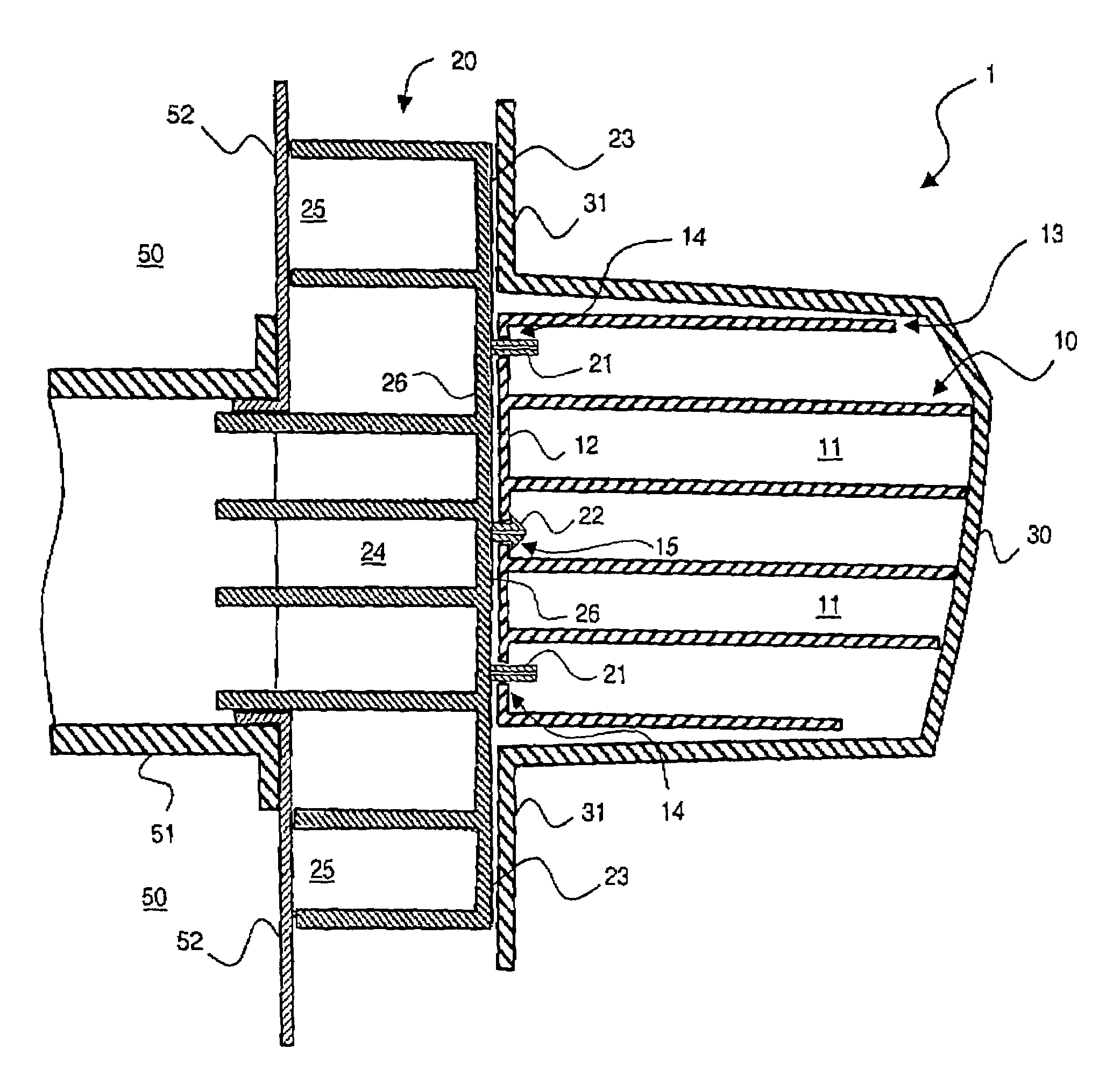
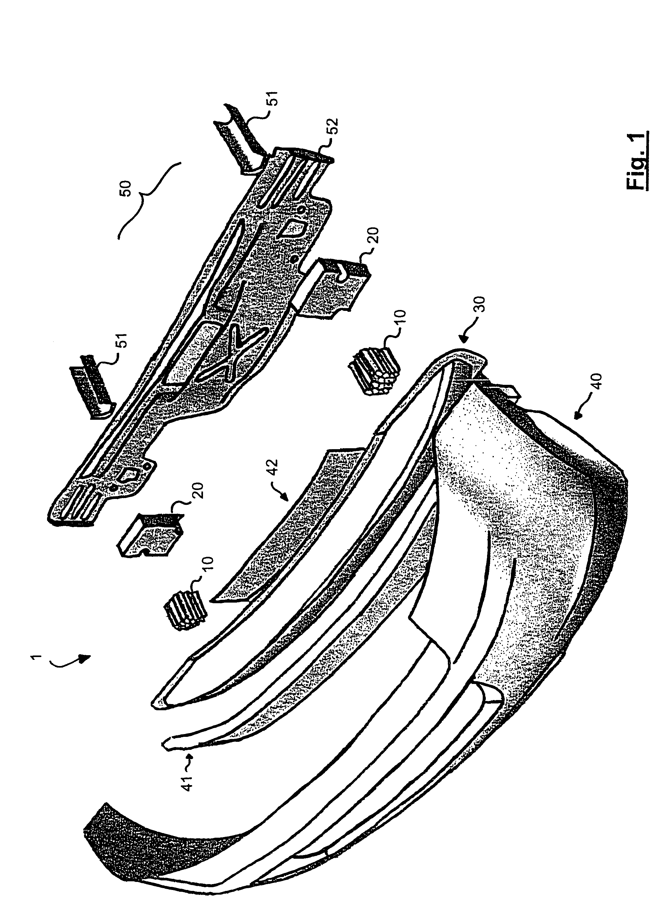
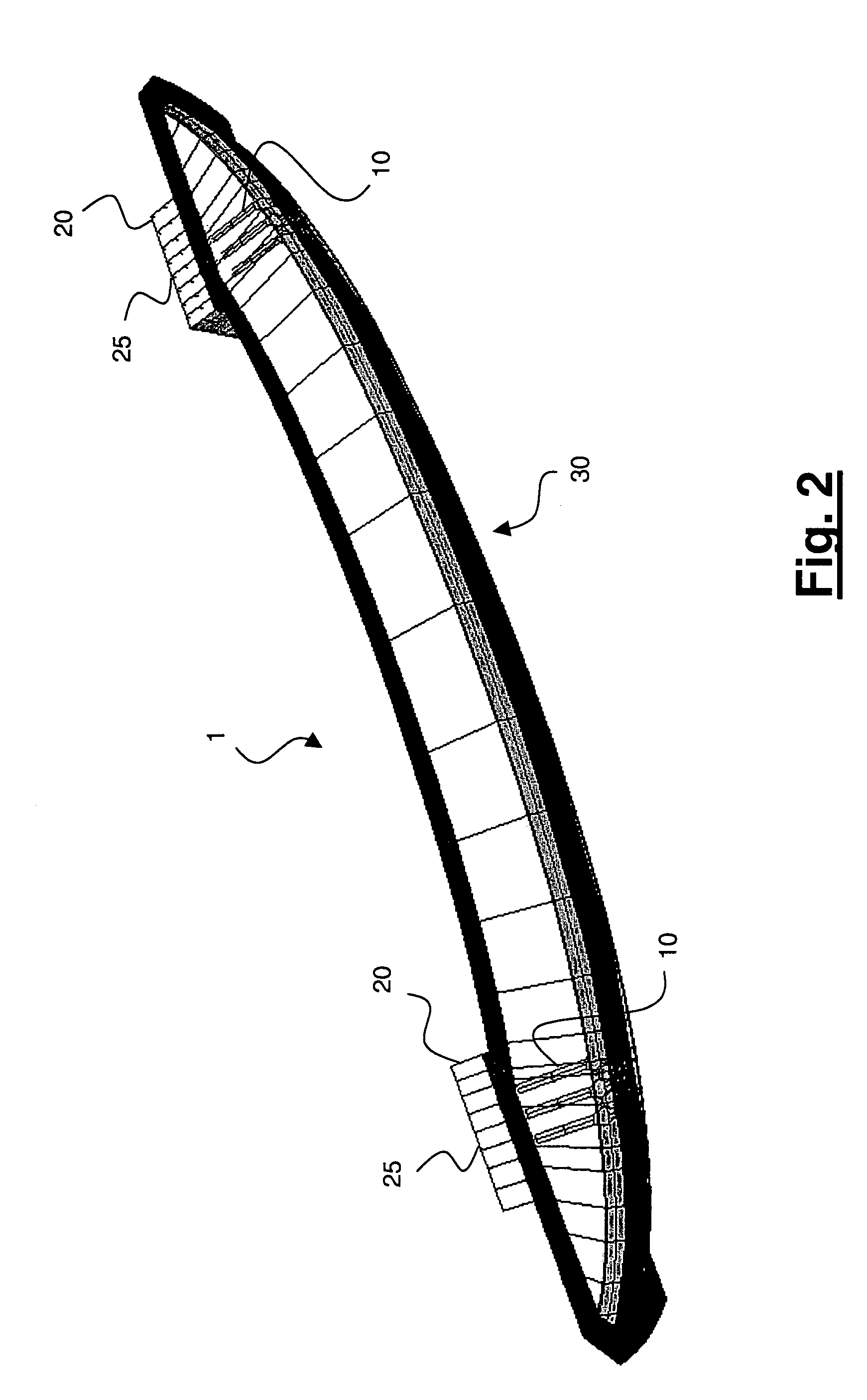
[0046]With reference to FIG. 1 and FIG. 2, the bumper assembly 1 according to the present invention comprises at least two crash boxes 10, at least two respective substantially indeformable connecting devices 20 for rigidly fixing said cross member to said chassis of the vehicle and a cross member 30. Profitably, the substantially indeformable connecting devices 20 are in the form of connecting plates 20. Conveniently, the bumper assembly 1 also comprises a bumper shield 40 which is suitably shaped.

[0047]Preferably, the bumper assembly 1 according to the invention also comprises an impact cushioning element 41 applied distally to the cross member 30.

[0048]Preferably, the bumper assembly 1 according to the invention also comprises a reinforcing element 42 applied proximally or distally to the cross member 30.

[0049]According to the present invention, the cross member 30 and, at least partially, the connecting plates 20, are made of a plastic material or the like. For the purpose of th...


PUM


Abstract

A bumper assembly for a vehicle and the corresponding vehicle comprising said bumper assembly are described. The assembly comprises: at least two crash boxes; a cross member made of a first plastic material which, during use, extends over a distance at least corresponding to that between the crash boxes; and at least two substantially indeformable connecting devices connected to said cross member for rigidly fixing said cross member to said chassis of the vehicle, wherein said at least two substantially indeformable connecting devices are connected to the cross member at positions corresponding to the crash boxes. In a preferred embodiment, the crash boxes and the connecting devices are made of plastic material.

Description

[0001]This application claims priority to IT Application No. M12003A001616, filed 6 Aug. 2003. The entire contents of this application is incorporated herein by reference.BACKGROUND AND SUMMARY[0002]The present invention relates to the cushioning of energy generated by bumpers in vehicles and in particular relates to an improved bumper assembly for vehicles as well as a vehicle comprising this bumper assembly and a method for protecting a vehicle from damage caused by impacts.[0003]It is known in the motor car industry to provide bumpers at the front and at the rear of a vehicle in order to cushion the energy resulting from an impact and limit as far as possible any damage to parts of the vehicle and injury to passengers and pedestrians who may be involved in the impact.[0004]At present, in particular, the attention of vehicle manufacturers is directed towards reducing the damage which a vehicle suffers following impacts at relatively low speeds, typically less than about 15–16 km / h...

Claims


Application Information

Patent Timeline
IPC IPC(8): B60R19/34B60R19/18
CPCB60R19/34B60R2019/1833
Inventor TONEATTI, JEAN LOUISVISMARA, MARIO
Owner VM PLASTICS
Why Eureka
Try Eureka