Vane structure of magnetron

a magnetron and vane structure technology, applied in the field of magnets, can solve the problems of unsatisfactory harmonic generation of microwaves, and achieve the effect of decreasing the generation of undesirable harmonics

Active Publication Date: 2006-11-14
SAMSUNG ELECTRONICS CO LTD
View PDF5 Cites 7 Cited by
  • Summary
  • Abstract
  • Description
  • Claims
  • Application Information

AI Technical Summary

Benefits of technology

[0009]Accordingly, it is an aspect of the present invention to provide a magnetron, in which a construction of outer ends of vanes brought into conta

Problems solved by technology

When the electric charges move through the two neighboring vanes and the portion of the positive polar body during the operation of the magnetron, undesirable har

Method used


Image

  • Vane structure of magnetron
  • Vane structure of magnetron
  • Vane structure of magnetron

Examples


Embodiment Construction

[0017]Reference will now be made in detail to the present preferred embodiments of the present invention, examples of which are illustrated in the accompanying drawings, wherein like reference numerals refer to like elements throughout.

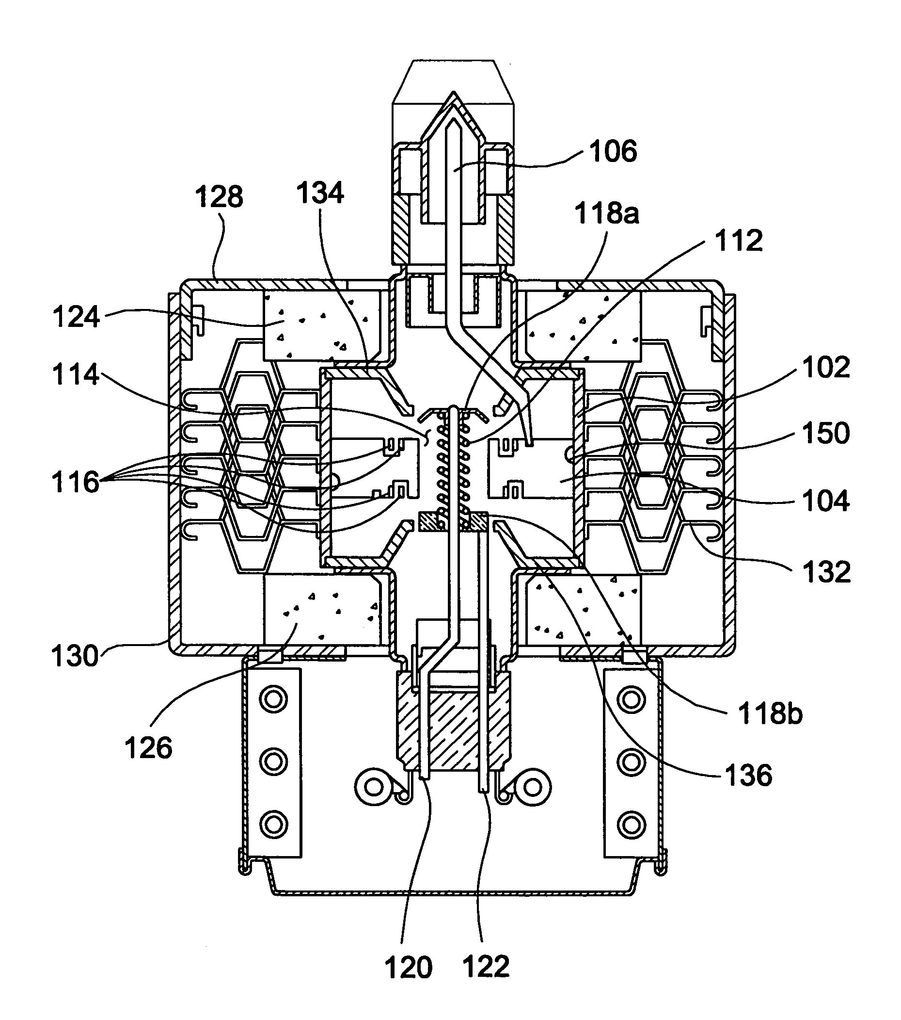
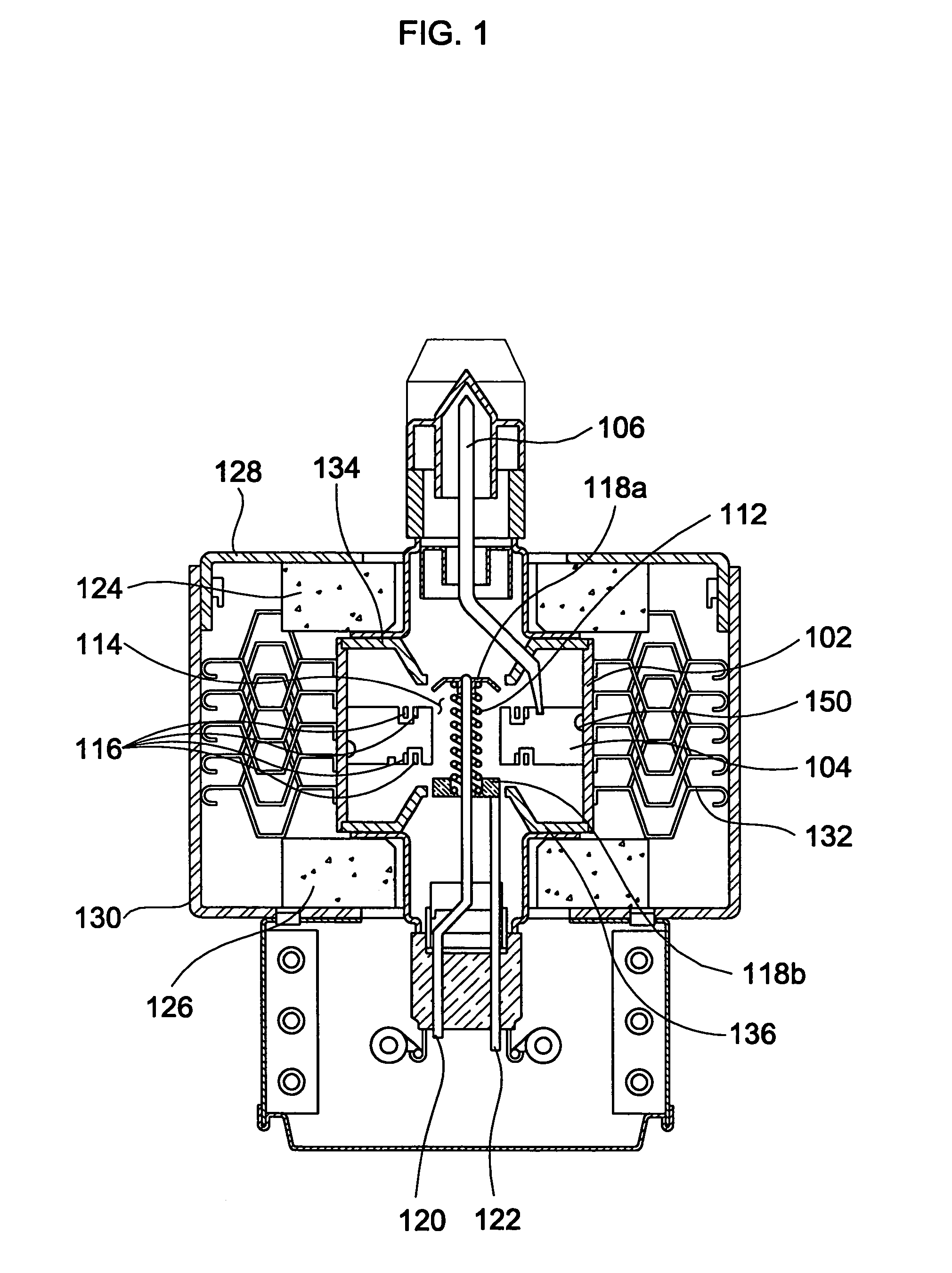
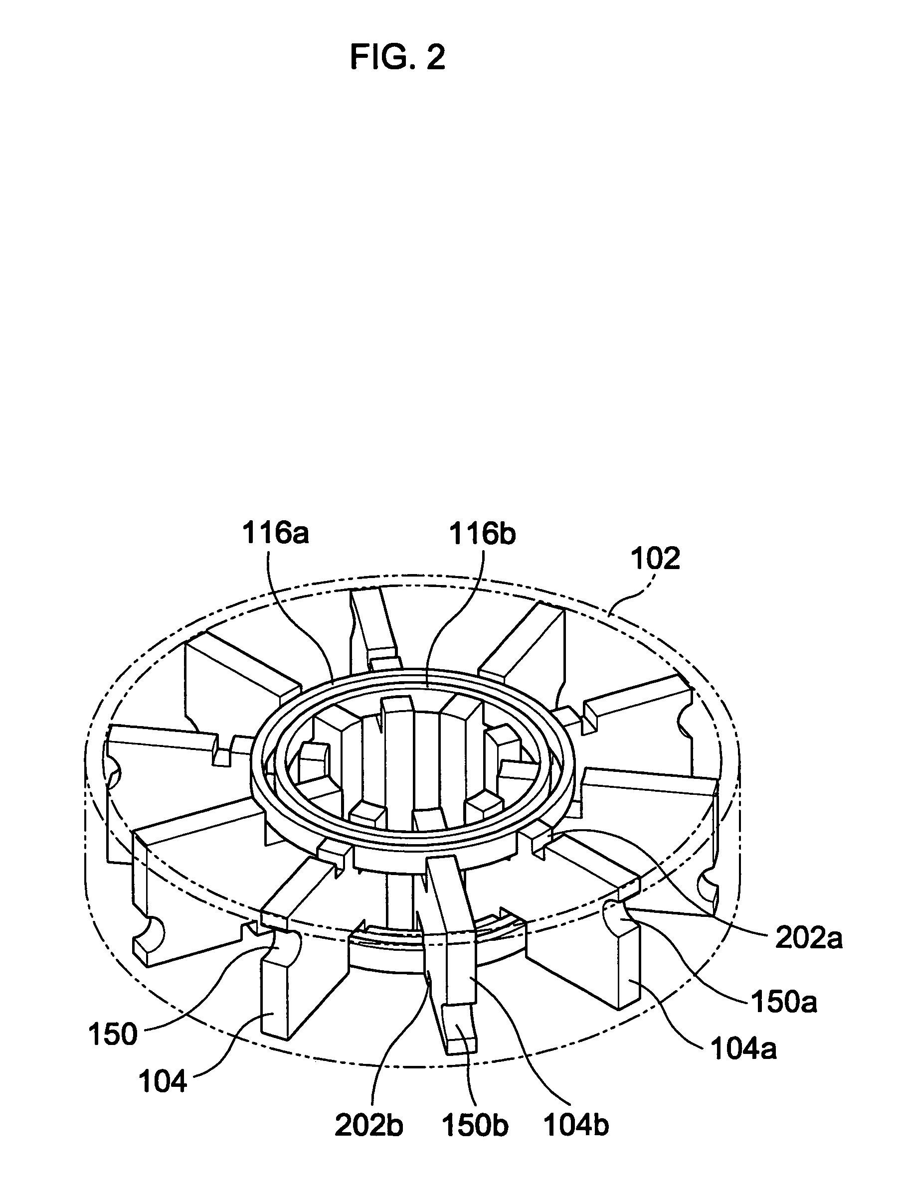
[0018]Hereinafter, a magnetron will be described with reference to FIGS. 1 through 4, according to an embodiment of the present invention. FIG. 1 is a sectional view of a magnetron, according to the embodiment of the present invention. As shown in FIG. 1, in the magnetron of the present invention, a plurality of vanes 104, which constitute a positive polar section together with a positive polar body 102, are radially arranged at regular intervals toward a central axis of the positive polar body 102, thus forming resonant circuits. An antenna 106 is connected to one of the vanes 104 to lead microwaves to the outside. Semi-circularly shaped electric field adjusting grooves 150 are provided on surfaces of outer ends of the vanes 104 brought into contact ...


PUM

PropertyMeasurementUnit
Magnetic fieldaaaaaaaaaa
Speedaaaaaaaaaa
Electric fieldaaaaaaaaaa

Abstract

A magnetron includes semi-circularly shaped electric field adjusting grooves provided on surfaces of outer ends of vanes brought into contact with an inner surface of a positive polar body to make distribution of an electric field uniform on the surfaces of the outer ends of the vanes. Accordingly, the electric field becomes uniform by the electric field adjusting grooves provided on the surfaces of the outer ends of the vanes, so that generation of undesirable harmonics is suppressed.

Description

CROSS-REFERENCE TO RELATED APPLICATIONS[0001]This application claims the benefit of Korean Application No. 2003-34550, filed May 29, 2003, in the Korean Intellectual Property Office, the disclosure of which is incorporated herein by reference.BACKGROUND OF THE INVENTION[0002]1. Field of the Invention[0003]The present invention relates, in general, to a magnetron and, more particularly, to a magnetron, in which a plurality of vanes positioned between a positive polar body and a negative polar section are radially arranged toward a central axis of the positive polar body, thereby generating microwaves.[0004]2. Description of the Related Art[0005]In general, magnetrons are high-frequency generators, and are widely used to generate microwaves in home appliances, such as microwave ovens, as well as in industrial applications, such as high-frequency heating apparatuses, particle accelerators and radars. In a magnetron, a plurality of vanes are arranged in a cylindrically shaped positive p...

Claims


Application Information

Patent Timeline
IPC IPC(8): H01J25/50C23C14/00H05B6/64H01J23/20H01J23/02H01J23/05H01J23/213H01J23/22H01J25/587
CPCH01J23/20H01J23/213H01J23/22H01J25/587H01J23/05
Inventor SHON, JONG-CHULLRAYSKIY, BORIS V.HA, HYUN-JUN
Owner SAMSUNG ELECTRONICS CO LTD
Why Eureka
Try Eureka