

Detachable seat for vehicle
- Summary
- Abstract
- Description
- Claims
- Application Information
AI Technical Summary
Benefits of technology
Problems solved by technology
Method used
Image

Examples
Embodiment Construction
[0038]A detachable seat for a vehicle according to an embodiment of the present invention will be discussed hereinafter with reference to the accompanying drawings.
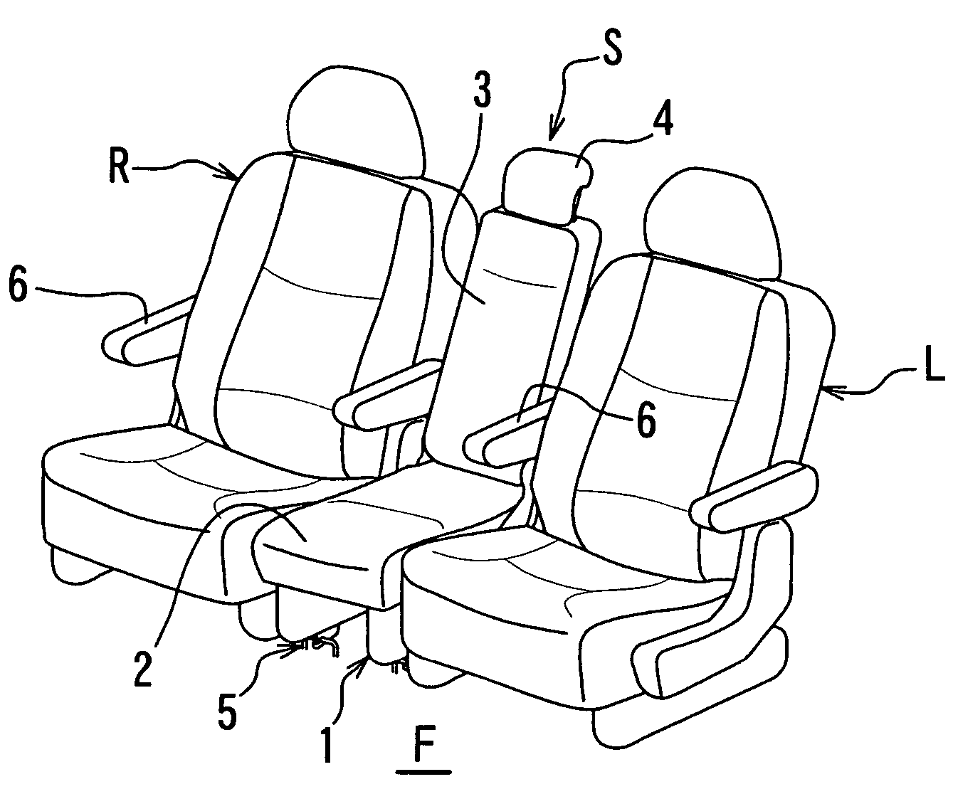
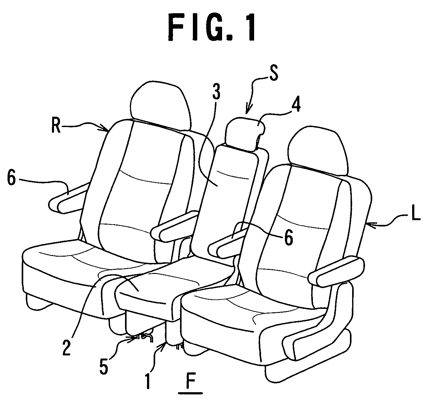
[0039]Referring to FIG. 1, there are illustrated three rear seats for a vehicle, which are arranged side by side on a vehicle floor F. In the illustrated example, the present invention is applied to a center seat S that is arranged between a first seat L and a second seat R. A width of the center seat S is narrower than that of each of the first and second seats L, R.
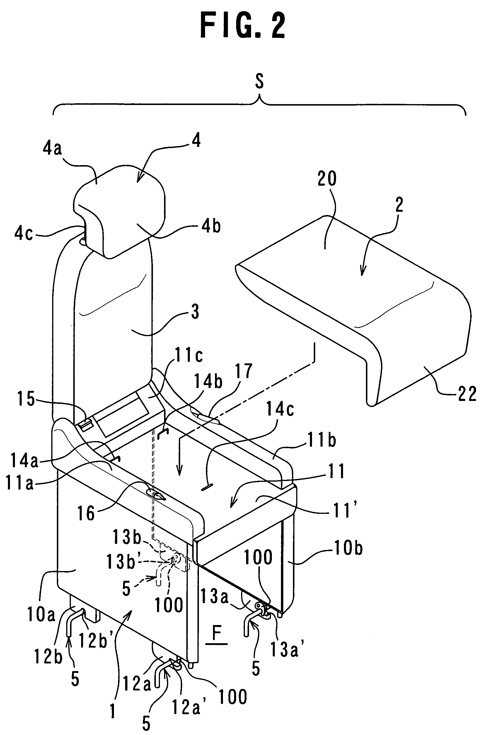
[0040]Referring to FIG. 2, the center seat S comprises seat leg means 1 serving as a seat base means, the seat leg means 1 including first and second spaced apart leg members 10a, 10b and a base member 11 arranged on the first and second leg members 10a, 10b, a seat cushion 2 detachably or removably mounted to the base member 11 of the seat leg means 1, a seat back 3, a height-adjustable headrest 4, first cooperating means for causing the center seat S to be ...
PUM
 Abstract
Description
Claims
Application Information