Electrical box assembly for recessing an electrical device

a technology for electrical devices and assembly parts, which is applied in the direction of electrical apparatus casings/cabinets/drawers, coupling device connections, machine supports, etc., can solve the problems of not meeting the needs of certain localities in which the electrical code has additional restrictions

Active Publication Date: 2007-01-23
ARLINGTON INDS
View PDF13 Cites 43 Cited by
  • Summary
  • Abstract
  • Description
  • Claims
  • Application Information

AI Technical Summary

Benefits of technology

[0008]A first object of the recessed electrical box assembly of the present invention is to provide an electrical box that positions an electrical device well within an exterior wall, thereby shielding the electrical device from impacts.
[0009]A second object is to provide an electrical box assembly including a cover that shields the electrical device and any electrical cords plugged therein from rain and other environme...

Problems solved by technology

Although a recessed electrical box of the type described in the aforementioned disclosures provided an adequate means for recessing an electrical devic...

Method used


Image

  • Electrical box assembly for recessing an electrical device
  • Electrical box assembly for recessing an electrical device
  • Electrical box assembly for recessing an electrical device

Examples


Embodiment Construction

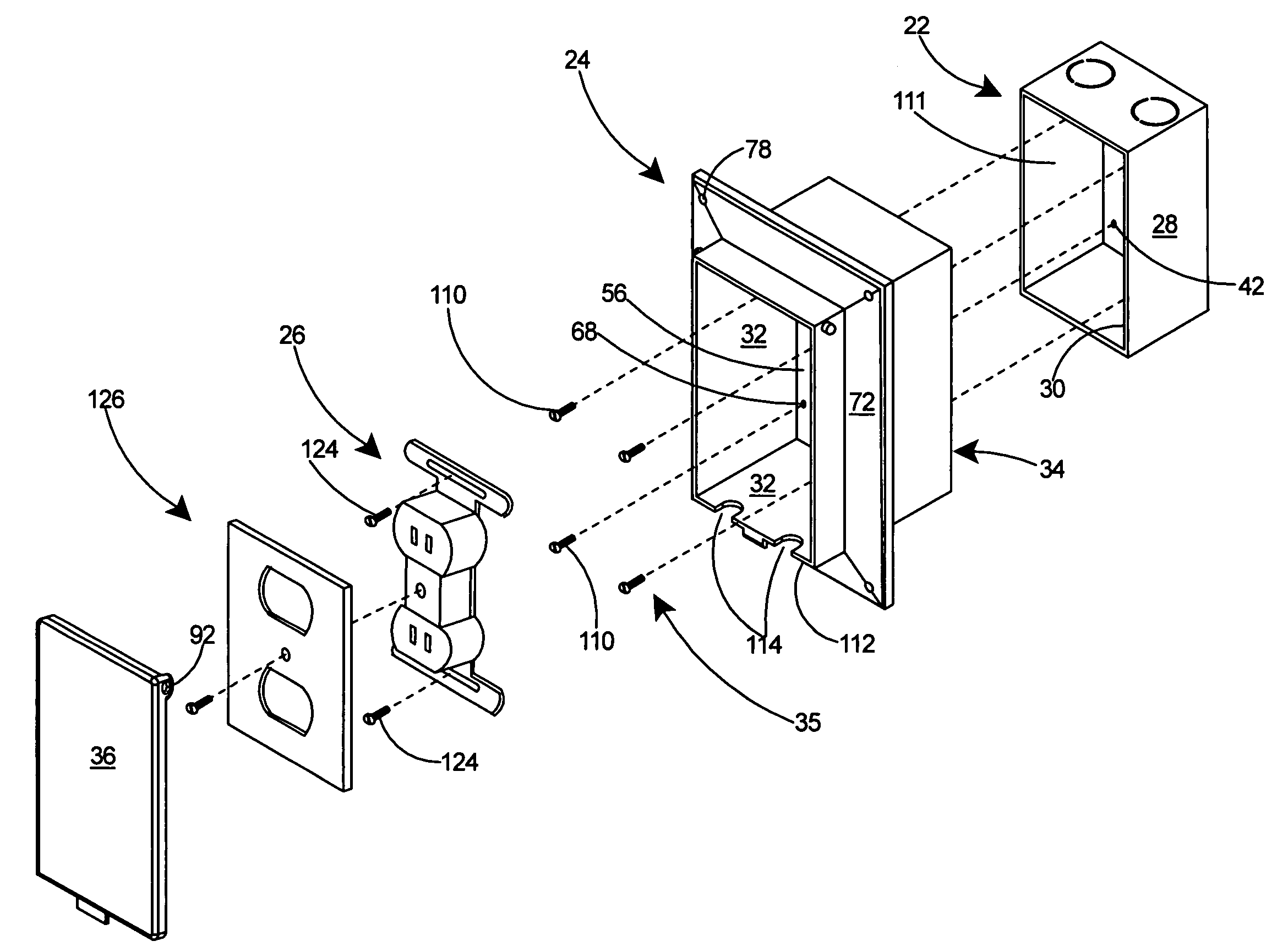
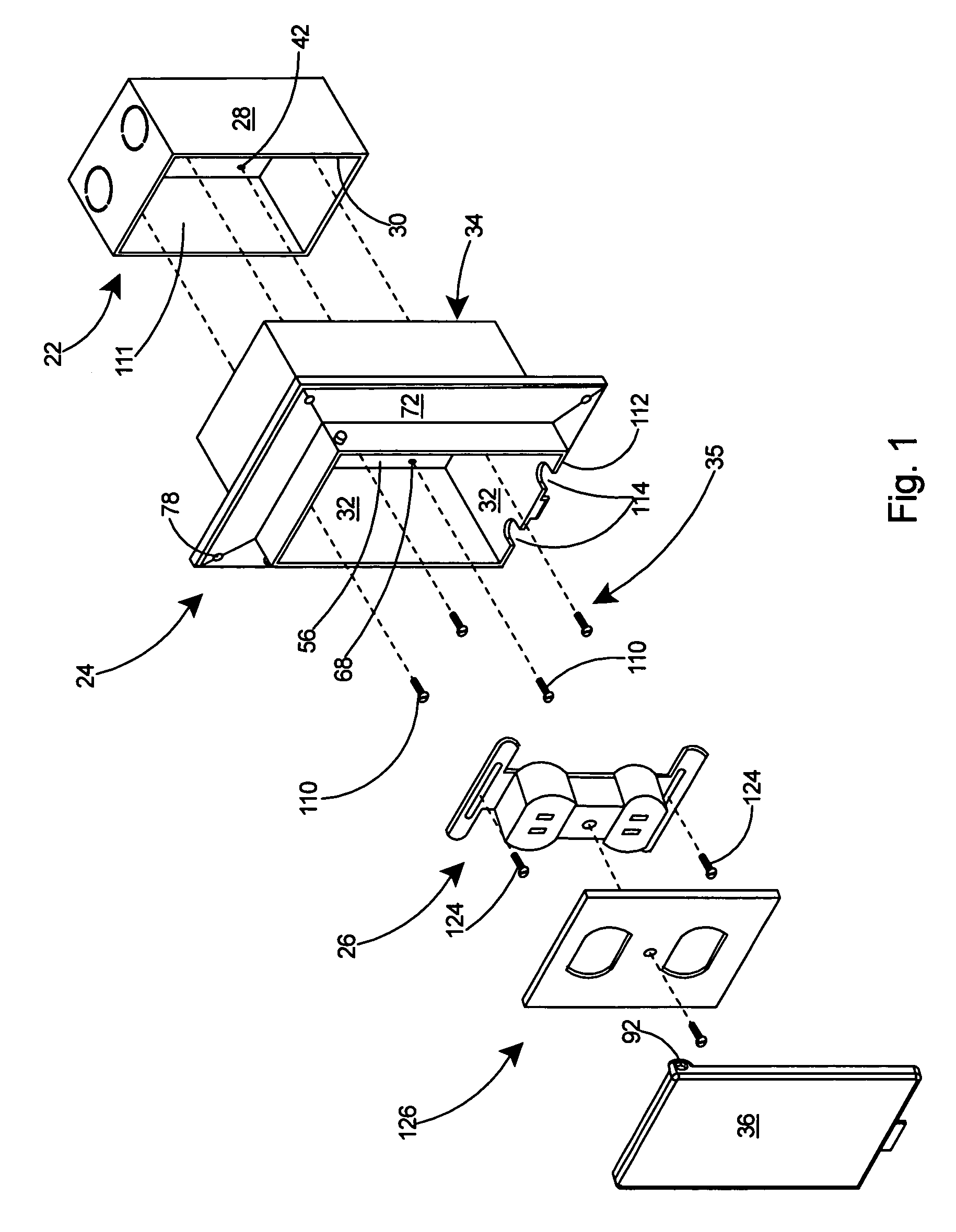
[0033]With reference to FIG. 16, the present invention comprises an electrical box assembly 20 including an inner box 22 and an outer box 24. The electrical box assembly 20 is used for recessing an electrical device 26 (partially shown) within a wall.

[0034]Referring to FIG. 1, the inner box 22 includes sidewalls 28 that terminate in a front edge 30. The outer box 24 includes sidewalls 32 and a rear abutment surface 34. A fastening arrangement 35 is provided for securing the outer box 24 to the inner box 22. The outer box 24 is secured to the inner box 22 in such a manner that the rear abutment surface 34 of the outer box 24 abuts the front edge 30 of the inner box 22. A cover 36, shown exploded away from the outer box 24 in FIG. 1, will be pivotally attached to the outer box 24.

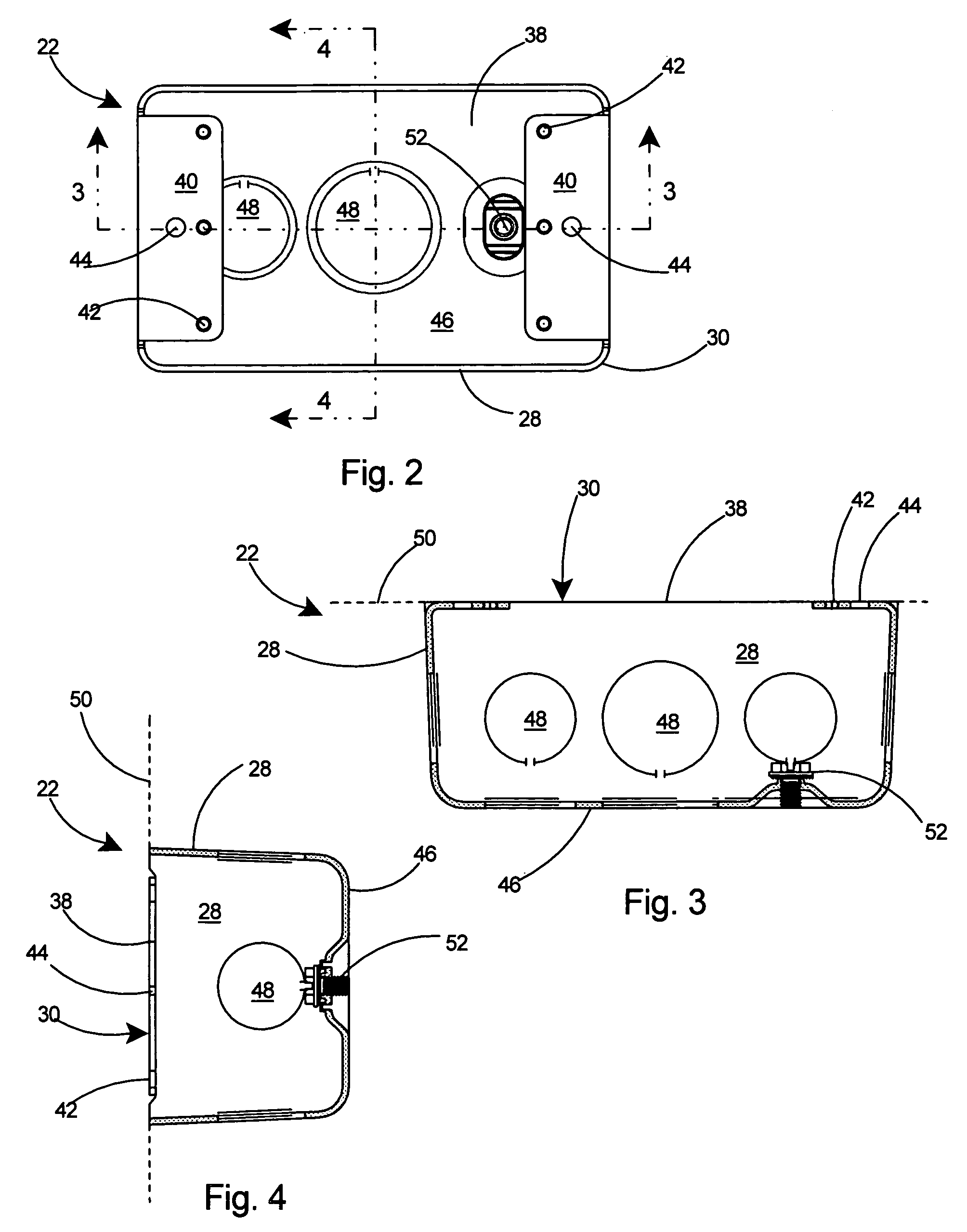
[0035]With reference to FIGS. 2–4, the inner box 22 includes a front opening 38 and panels 40 that extend orthogonally from the front edge 30 of the inner box 22 into the front opening 38. The inner box 22 is...


PUM


Abstract

A two-piece electrical box assembly for recessing a duplex receptacle or similar electrical device within a wall. An inner box portion is constructed of metal and includes sidewalls and a back wall defining a cavity therein. The cavity is capable of receiving the electrical device therein. An outer box portion includes an outward extending flange and provides a protective enclosure surrounding the inner box portion and the electrical device within the inner box portion. The electrical box assembly is capable of recessing into a hole in a wall until the outward extending flange is flush with the wall. A cover on the outer box portion can be closed to provide a rainproof enclosure therein for the plug ends of electrical cords while they are connected to the electrical device.

Description

[0001]This application is a Continuation-In-Part of U.S. patent application Ser. No. 11 / 264,857 filed Nov. 2, 2005 and still pending, which is a Continuation-In-Part of U.S. patent application Ser. No. 11 / 246,985, filed Oct. 7, 2005 and still pending, which is a Continuation-In-Part of U.S. patent application Ser. No. 11 / 185,256, filed Jul. 20, 2005 and still pending, which is a Continuation-In-Part of U.S. patent application Ser. No. 11 / 102,392, filed Apr. 8, 2005 now abandoned, which is a Continuation-In-Part of U.S. patent application Ser. No. 11 / 070,344, filed Mar. 2, 2005 and now U.S. Pat. No. 6,965,078, which is a Continuation-In-Part of U.S. patent application Ser. No. 11 / 009,116 filed Dec. 10, 2004 now U.S. Pat. No. 7,005,578, which is a Continuation-In-Part of U.S. patent application Ser. No. 10 / 863,942 filed Jun. 9, 2004 and now U.S. Pat. No. 6,956,171.FIELD OF THE INVENTION[0002]This invention relates to assemblies for the mounting of electrical devices and specifically t...

Claims


Application Information

Patent Timeline
IPC IPC(8): H01H9/02
CPCH02G3/121H02G3/14Y10S248/906
Inventor GRETZ, THOMAS J.
Owner ARLINGTON INDS
Why Eureka
Try Eureka