Fan blade modifications

a technology of fan blades and modifications, which is applied in the direction of wind motors with parallel air flow, waterborne vessels, machines/engines, etc., can solve the problems of people who work in large structures such as warehouses and manufacturing plants being exposed to working conditions that are wide, air temperature, and being unable to maintain a healthy or otherwise desirable body temperatur

Active Publication Date: 2007-08-07
DELTA T
View PDF14 Cites 122 Cited by
  • Summary
  • Abstract
  • Description
  • Claims
  • Application Information

AI Technical Summary

Problems solved by technology

People who work in large structures such as warehouses and manufacturing plants may be exposed to working conditions that range from being uncomfortable to hazardous.
On a hot day, the inside air temperature may reach a point where a person or other animal is unable to maintain a healthy or otherwise desirable body temperature.
Moreover, some activities that occur in these environments, such as welding or operating internal combustion engines, may create airborne contaminants that can be deleterious to those exposed.
The effects of airborne contaminants may be magnified if the air flow in the area is less than ideal.
In certain structures and environments, a problem may arise with heat gathering and remaining near the ceiling of the structure.
This may be of concern where the area near the floor of the structure is relatively cooler.
Those of ordinary skill in the art will immediately recognize disadvantages that may arise from having this or other imbalanced air / temperature distribution.

Method used


Image

  • Fan blade modifications
  • Fan blade modifications
  • Fan blade modifications

Examples


Embodiment Construction

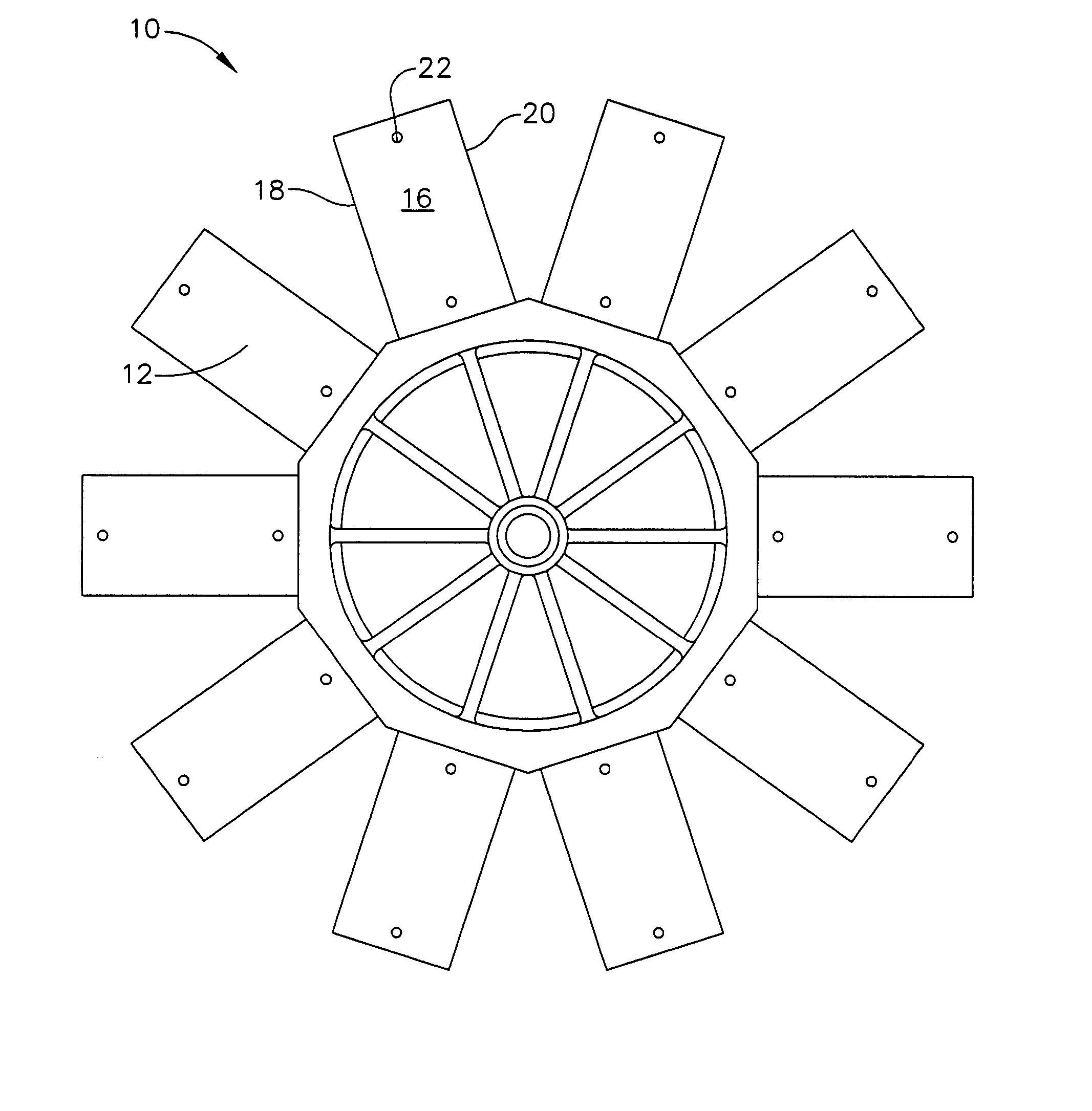
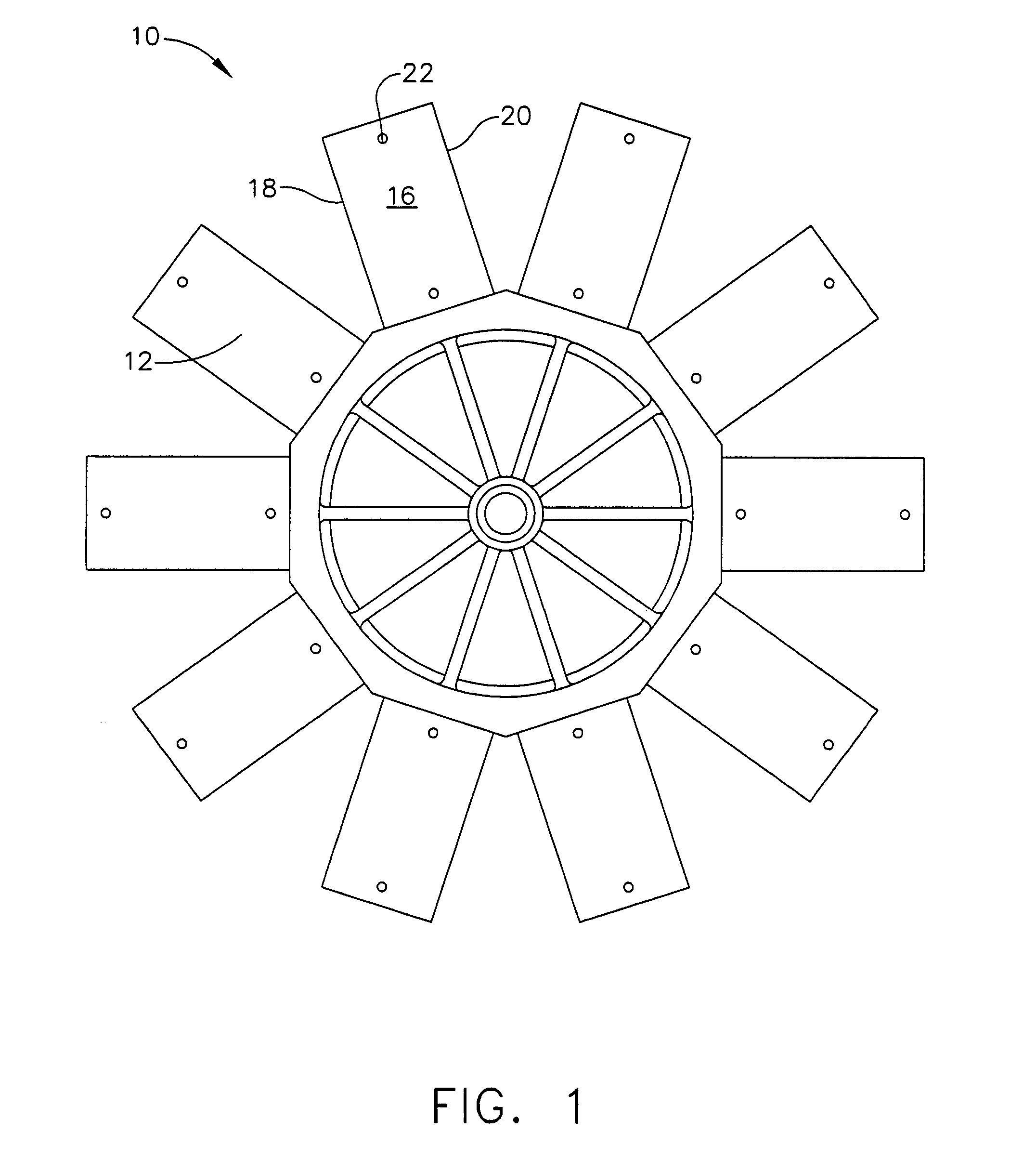
[0019]Referring now to the drawings in detail, wherein like numerals indicate the same elements throughout the views, FIG. 1 shows exemplary fan hub 10, which may be used to provide a fan having fan blades 30 or 50. In the present example, fan hub 10 includes a plurality of hub mounting members 12 to which fan blades 30 or 50 may be mounted. In one embodiment, fan hub 10 is coupled to a driving mechanism for rotating fan hub 10 at selectable or predetermined speeds. A suitable hub assembly may thus comprise hub 10 and a driving mechanism coupled to hub 10. Of course, a hub assembly may include a variety of other elements, including a different hub, and fan hub 10 may be driven by any suitable means. In addition, fan hub 10 may have any suitable number of hub mounting members 12.

[0020]As shown in FIGS. 1 through 3, each hub mounting member 12 has top surface 14 and bottom surface 16, which terminate into leading edge 18 and trailing edge 20. In addition, each hub mounting member 12 i...


PUM


Abstract

A winglet includes a vertical member and a mounting member. The mounting member is configured to facilitate the mounting of the winglet to the tip of a fan blade. The vertical member is configured to extend perpendicularly relative the tip of a fan blade. Adding winglets to fan blades may improve the aerodynamics of the fan blades, and thereby increase efficiencies of a fan.

Description

PRIORITY[0001]This application claims priority from the disclosure of U.S. Provisional Patent Application Ser. No. 60 / 589,945, entitled “Fan Blades and Modifications,” filed Jul. 21, 2004, which is incorporated by reference herein.BACKGROUND OF THE INVENTION[0002]The present invention relates generally to fan blades and fan blade modifications, and is particularly directed to an airfoil suitable for use with a fan blade and a winglet suitable for use with a fan blade.[0003]People who work in large structures such as warehouses and manufacturing plants may be exposed to working conditions that range from being uncomfortable to hazardous. The same may also apply in agricultural settings, such as in a structure that is full of livestock. On a hot day, the inside air temperature may reach a point where a person or other animal is unable to maintain a healthy or otherwise desirable body temperature. In areas where temperatures are uncomfortably or unsafely high, it may be desirable to ha...

Claims


Application Information

Patent Timeline
Patent Type & Authority Patents(United States)
IPC IPC(8): F01D1/00
CPCF03B17/063F04D29/388Y02E10/28F04D25/088F04D29/34Y02E10/20
Inventor AYNSLEY, RICHARD MICHAEL
Owner DELTA T
Why Eureka
Try Eureka