Highly collapsible ambulatory assistive walker apparatus

a walker and assistive technology, applied in the field of collapsible walker devices, can solve the problems of complex multi-step process of collapsing such walkers, and achieve the effect of improving ambulatory capabilities

Inactive Publication Date: 2007-12-11
GALE BRADLEY D
View PDF10 Cites 83 Cited by
  • Summary
  • Abstract
  • Description
  • Claims
  • Application Information

AI Technical Summary

Benefits of technology

[0027]The first and second front cross braces of the front leg collapsing assembly are rigid, and define a front leg collapsing plane, which includes the first and second front support legs, and the first and second cross braces. The first and second front cross braces may be formed from tubular members, wherein at the central pivot connection regions thereof, the tubular members are flattened, thereby facilitating the pivot connection and operation between them. The first and second cross braces may also be formed into slight S-shapes, so as to provide a greater angle of rotation between them, thereby providing a greater degree of collapsibility of the walker apparatus. The central pivot connection between the first and second front cross brace members may be made by use of a suitable fastener, such as a rivet or a screw and nut assembly. The pivot connection between the first and second cross braces may be provided with protective and / or ornamental covers. The central pivot connection between the first and second cross braces is made at substantially the midpoints of the first and second cross braces, i.e. the lengths of the cross braces from the central pivot connection to the respective ends of each brace may be substantially equal.
[0030]The technique and apparatus is advantageous because it enables the provision of a highly featured, structurally strong walker apparatus that can be collapsed into a compact shape with a simple continuous motion and operation of one of the subassemblies. As a result of the invention, disabled and / or elderly persons may have improved ambulatory capabilities in a variety of locations.

Problems solved by technology

The collapsing of such walkers is often a complex multi-step process: various components of the particular collapsible walker must be individually collapsed and / or retracted.
This collapsing often entails the loosening of various fasteners, and the subsequent retightening of such fasteners when the walker or its subcomponent is collapsed.

Method used


Image

  • Highly collapsible ambulatory assistive walker apparatus
  • Highly collapsible ambulatory assistive walker apparatus
  • Highly collapsible ambulatory assistive walker apparatus

Examples


Embodiment Construction

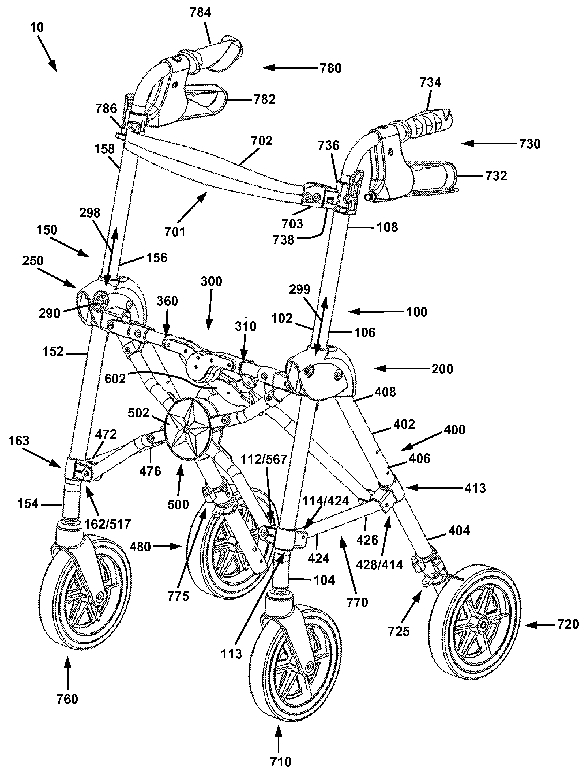
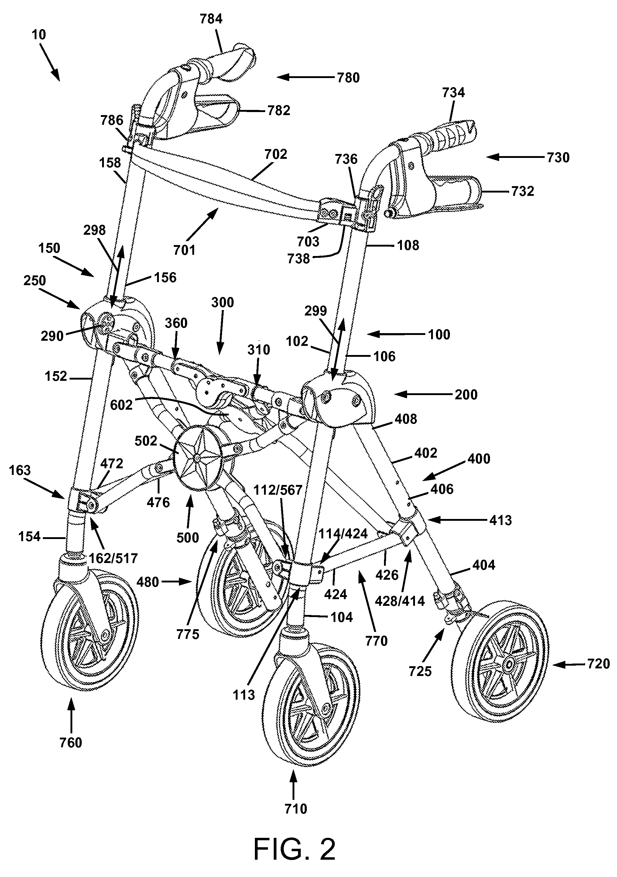
[0063]For a general understanding of the present invention, reference is made to the drawings. In the drawings, like reference numerals have been used throughout to designate identical elements.

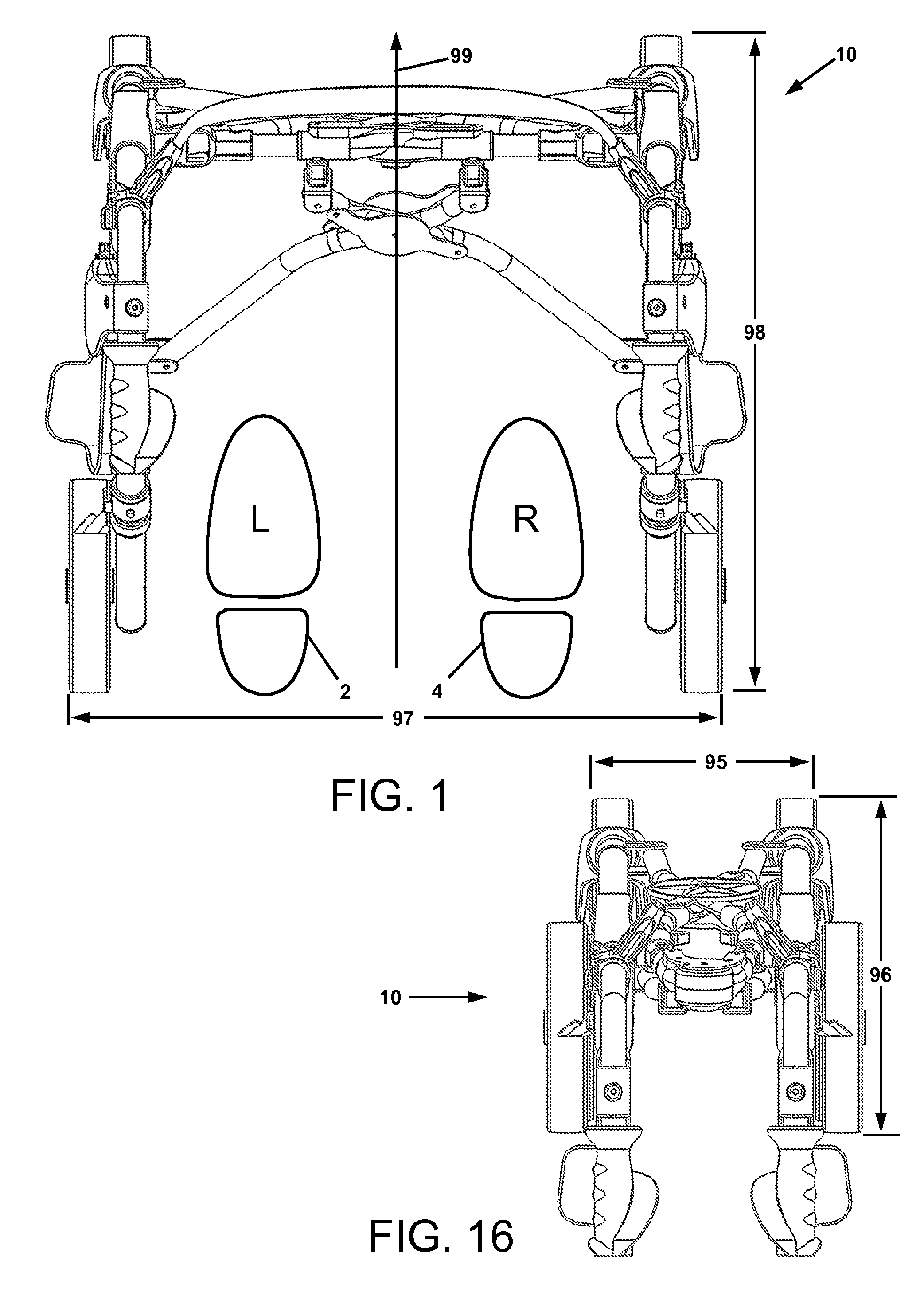
[0064]As used herein, the term “open” with respect to a walker apparatus is meant to indicate that the walker is deployed on a horizontal surface and ready for use with all four leg assemblies rigidly engaged with each other.

[0065]As used herein, the term “collapsed” with respect to a walker apparatus is meant to indicate the opposite of “open”, i.e. the device is retracted to its most compact configuration for the purpose of storage or transportation in a confined space.

[0066]As used herein, the terms “hingably” and “pivotably,” and hingeable” and pivotable” are used interchangeably, and, with respect to a pair of operatively connected parts are meant to indicate that the first part of the pair rotates with respect to the second part at their common attachment point, as occurs with a hinge m...


PUM


Abstract

A walker apparatus comprised of a first front support leg assembly, a second front support leg assembly, a first sliding joint, a second sliding joint, a central hinge joint, a first rear support leg assembly, a second rear support leg assembly, a first support member, a second support member, a front leg collapsing assembly, and a rear leg collapsing assembly. The walker apparatus is adapted to be is collapsed to a compact shape in a continuous collapsing motion.

Description

[0001]This invention relates in one embodiment to an walker apparatus, and more particularly to a highly accessorized walker apparatus that is collapsible to a compact shape in a continuous collapsing motion.BACKGROUND OF THE INVENTION[0002]1. Field of the Invention[0003]A collapsible walker apparatus for providing ambulatory assistance to a person having otherwise limited mobility.[0004]2. Description of Related Art[0005]There are many different types of apparatus used to provide ambulatory assistance to the elderly and the infirm. One type of apparatus, known generally as a walker, is used by a person standing in an upright (walking) position to provide assistance in walking, or otherwise moving carefully in forward, backward, or sideways directions. Typically, a walker includes a four-legged frame support, and support bars which the user grips with his / her hands as he / she uses the device for walking support.[0006]For some time now, walkers in various configurations have been made...

Claims


Application Information

Patent Timeline
Patent Type & Authority Patents(United States)
IPC IPC(8): B62B7/06
CPCA61H3/04A61H2201/0161A61H2003/046
Inventor GALE, BRADLEY D.
Owner GALE BRADLEY D
Why Eureka
Try Eureka