Radio-controlled timepiece and method of adjusting the time kept by a radio-controlled timepiece

a radio-controlled timepiece and timepiece technology, applied in the direction of setting time indication, instruments, horology, etc., can solve the problem that the time and power consumed in adjusting the time is large, and achieve the effect of improving the accuracy of the adjusted tim

Active Publication Date: 2007-12-11
SEIKO EPSON CORP
View PDF11 Cites 23 Cited by
  • Summary
  • Abstract
  • Description
  • Claims
  • Application Information

AI Technical Summary

Benefits of technology

[0036]As described above, a radio-controlled timepiece and time adjustment method according to the present invention can adjust the time based on signals received in a short period and can also improve the accuracy of the adjusted time.

Problems solved by technology

Adjusting the time therefore consumes much time and power.

Method used


Image

  • Radio-controlled timepiece and method of adjusting the time kept by a radio-controlled timepiece
  • Radio-controlled timepiece and method of adjusting the time kept by a radio-controlled timepiece
  • Radio-controlled timepiece and method of adjusting the time kept by a radio-controlled timepiece

Examples


first embodiment

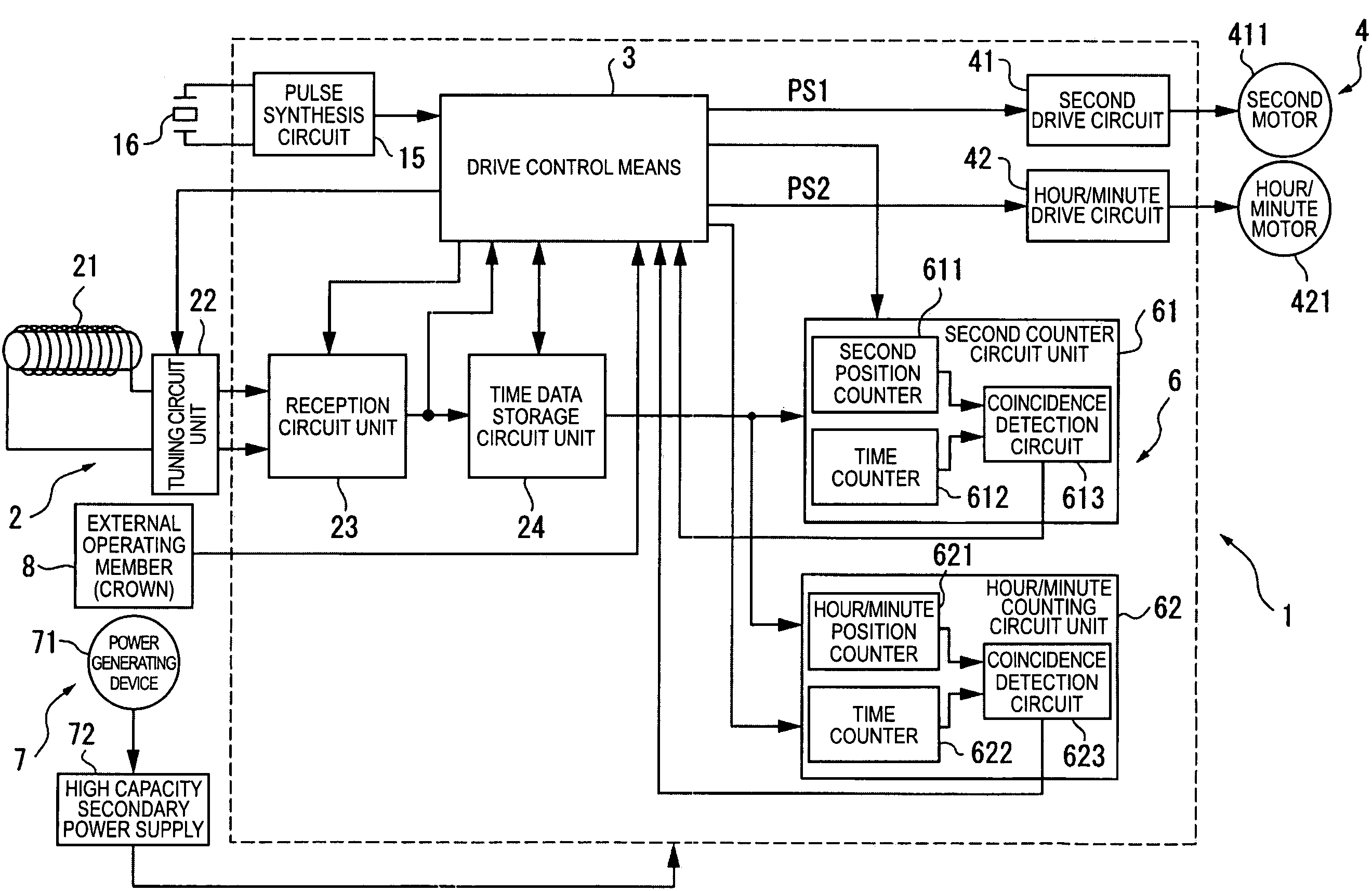
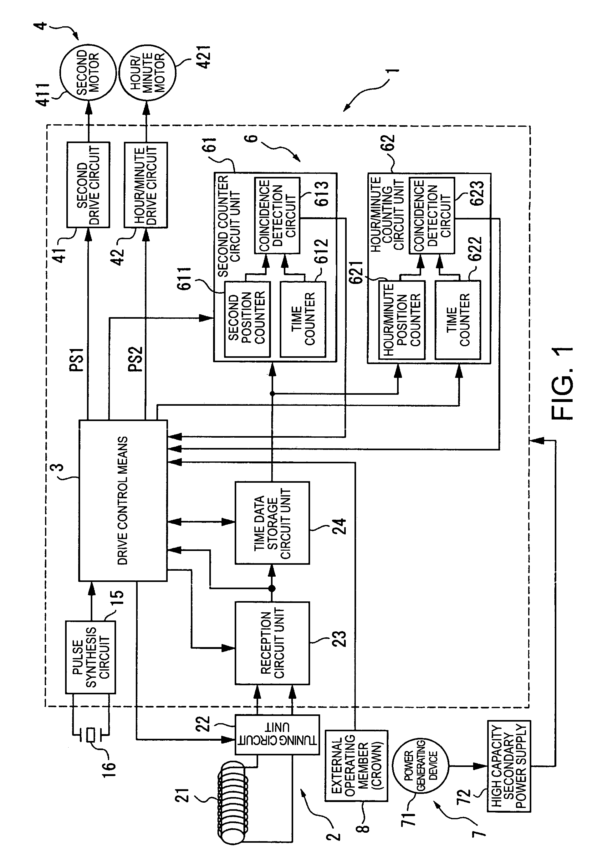
[0072]FIG. 1 is a block diagram showing the arrangement of a radio-controlled timepiece 1 as an electronic device according to a first embodiment of the invention.

[0073]The radio-controlled timepiece 1 of the present invention has the same basic arrangement as a common radio-controlled timepiece, including a time signal receiving means 2 for receiving radio frequency information containing time information (external wireless information), a drive control means 3, a mechanical drive means 4 for driving the hands, a counter means 6 for keeping time, a power supply means 7 for supplying power, and an external operating member 8 such as a crown or button.

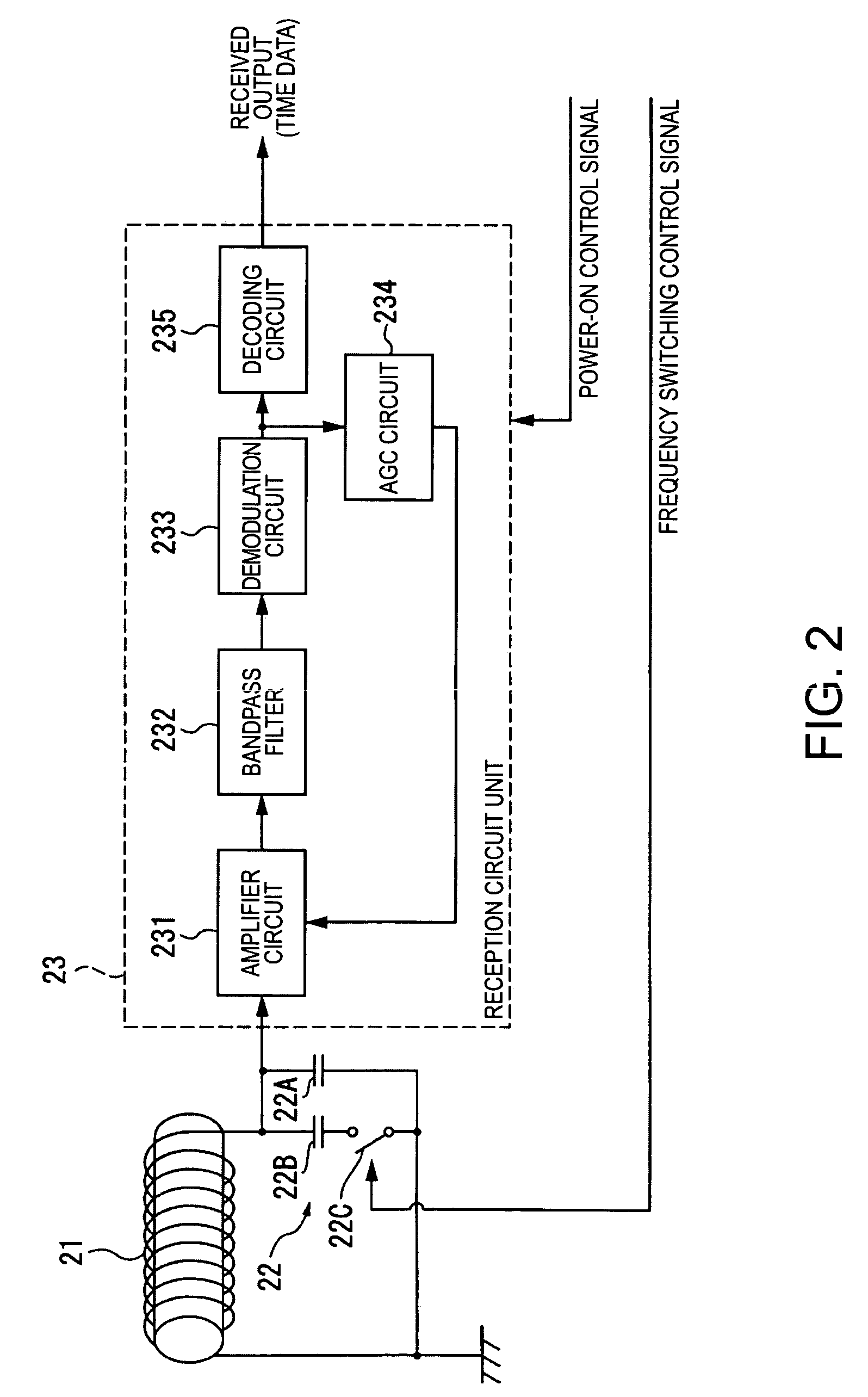
[0074]The time signal receiving means 2 has an antenna 21, a tuning circuit unit 22 such as a capacitor for tuning to the signal received by the antenna 21, a reception circuit unit 23 for processing information received by the antenna 21, and a time data storage circuit unit 24 for evaluating and storing the time data processed by the ...

second embodiment

[0163]A radio-controlled timepiece 1 according to a second embodiment of the invention is described next.

[0164]Identical or functionally similar parts in this and the previous embodiment are identified by like reference numerals, and further description thereof is omitted or abbreviated.

[0165]The radio-controlled timepiece 1 according to this second embodiment improves the pulse timing detection unit 331 so that the rising edge timing of the rectangular wave pulses can be accurately detected even when the reception signal output by the reception circuit unit 23 has a low S / N ratio and contains noise as shown in FIG. 10.

[0166]When the S / N ratio is low as shown in FIG. 10, the signal contains noise and the pulse width is narrower than in the actual time code. In the normal JJY time code the narrowest pulse width is 200 msec as shown in FIG. 5. As a result, any pulses with a width shorter than 200 msec can be dropped because they represent noise.

[0167]After detecting the rising edges o...


PUM


Abstract

A radio-controlled timepiece can adjust the time with a short reception process while also reducing the likelihood of incorrect adjustment. The radio-controlled timepiece has a reception control means 31, time information updating means 32, time adjustment storage means 33, and time display means. The reception control means 31 has a simple time adjustment means 330 that is driven within a predetermined time of the last successful signal reception, and a normal time adjustment means 320 that is driven when this predetermined time has passed. The simple time adjustment means 330 has a pulse timing detection unit 331, a offset calculation unit 332, a offset evaluation unit 333, and a seconds information adjustment unit 334. The pulse timing detection unit 331 detects the reference timing, which is the timing of the rising edge or falling edge of rectangular wave pulses in the received time code. The offset calculation unit 332 calculates the difference between this reference timing and the timing of the seconds unit in the internally kept time. The offset evaluation unit 333 determines if this offset is within a tolerance range. The seconds information adjustment unit 334 adjusts the seconds unit of the internal time based on the offset if the offset is within the tolerance range.

Description

BACKGROUND[0001]1. Technical Field[0002]The present invention relates to a radio-controlled timepiece and to a method of adjusting the time displayed by a radio-controlled timepiece.[0003]2. Related Art[0004]Radio-controlled timepieces that receive a radio signal containing time information (a longwave standard time signal) and automatically adjust and display the time based on the received time information are known from the literature.[0005]A standard time signal is output, for example, at one second intervals, uses three different pulse widths to indicate the time, and takes one minute to send one complete time code.[0006]Determining the time from these standard time signals typically requires continuously receiving the time signal for several minutes in order to receive the full time code plural times consecutively so that plural time codes can be compared to ensure the accuracy of the received time information. Adjusting the time therefore consumes much time and power.[0007]Add...

Claims


Application Information

Patent Timeline
Patent Type & Authority Patents(United States)
IPC IPC(8): G04C11/02G04G5/00G04G21/04G04R20/00G04R20/10
CPCG04G5/002G04R20/10G04G21/04G04G7/02
Inventor FUJISAWA, TERUHIKO
Owner SEIKO EPSON CORP
Why Eureka
Try Eureka