Oscillator circuit with tuneable signal delay means

a delay means and oscillator circuit technology, applied in the direction of oscillator generators, pulse automatic control, logic circuits, etc., can solve the problems of increasing the sensitivity of parameter variations, difficult frequency tuning with maintained performance, and circuit becomes very sensitive to component variations, etc., to achieve optimal performance of the circuit, simplify the effect of maintaining performance and high degree of precision

Inactive Publication Date: 2008-04-01
HIGHBRIDGE PRINCIPAL STRATEGIES LLC AS COLLATERAL AGENT
View PDF5 Cites 5 Cited by
  • Summary
  • Abstract
  • Description
  • Claims
  • Application Information

AI Technical Summary

Benefits of technology

[0009]By means of the invention, the delay in the oscillator circuit can be controlled with a high degree of precision in an automated fashion in order to achieve the desired phase and thus the optimal performance of the circuit. The embodiments disclosed automatically adjust to the correct phase, and are thus less sensitive to component variations in, for example, processing, temperature or ageing. In addition, tuning of the oscillation frequency of the proposed embodiments of the invention with maintained performance will become simplified.

Problems solved by technology

A problem with delay lines in oscillators is that the delay provided by the delay lines must be very precise, due to the fact that the delay is optimal for a single frequency only, which thus makes the circuit sensitive, and necessitates a high degree of precision in the design and manufacture of the delay lines.
In addition, the circuit becomes very sensitive to component variations in, for example, temperature and ageing.
Also, in circuits of the kind described, frequency tuning with maintained performance tend to be difficult, and the sensitivity for parameter variations tends to increase with increased performance of the oscillator circuit.

Method used


Image

  • Oscillator circuit with tuneable signal delay means
  • Oscillator circuit with tuneable signal delay means
  • Oscillator circuit with tuneable signal delay means

Examples


embodiment 200

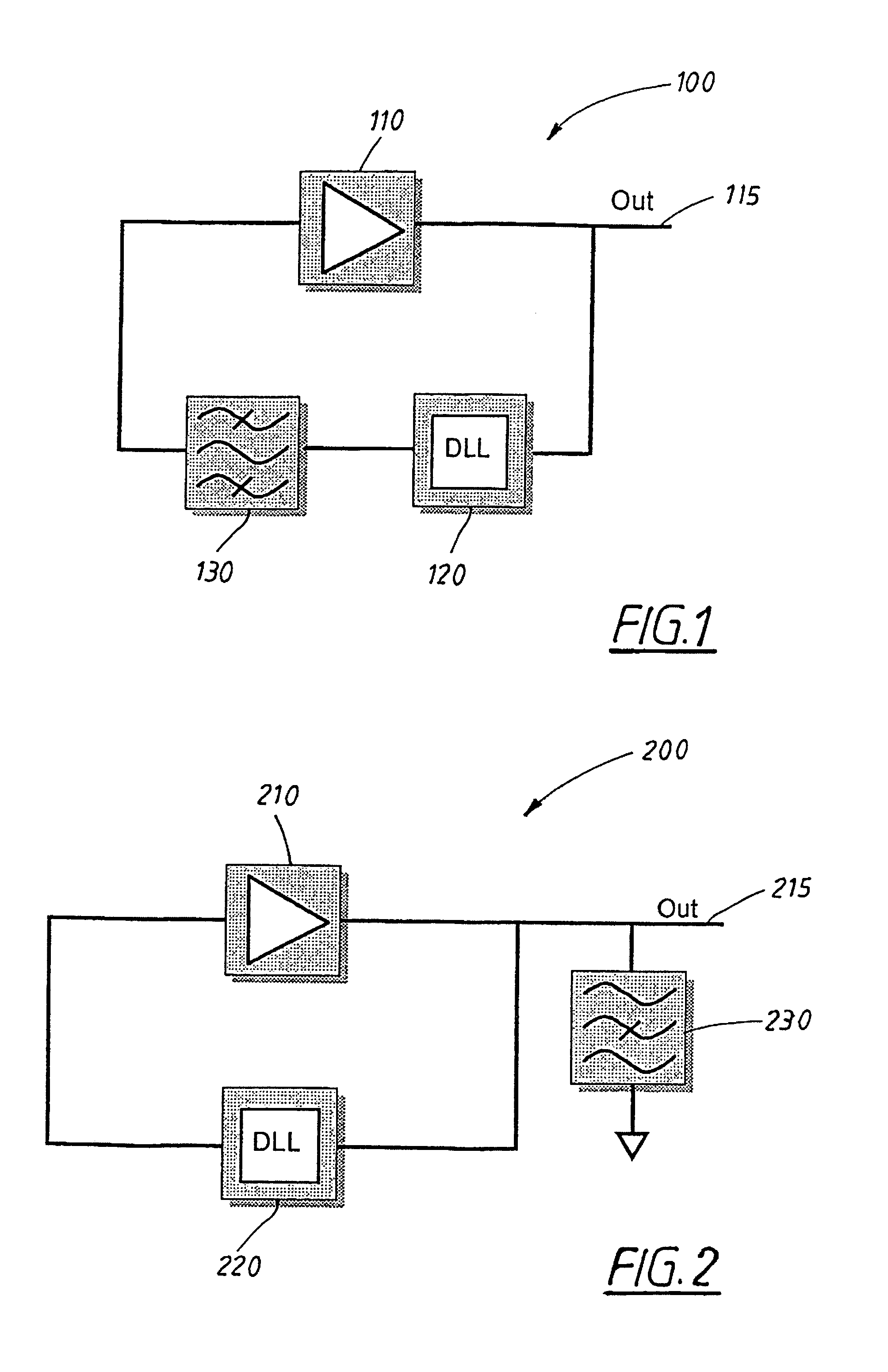
[0029]FIG. 2 shows an alternative embodiment 200 of an oscillator circuit based on the principle of a positive feedback amplifier oscillator. Similarly to the oscillator circuit 100 of FIG. 1, the oscillator circuit 200 of FIG. 2 comprises an amplifier 210 and a DLL 220 which forms a feed-back loop with the amplifier, feeding back to the input of the operational amplifier the output signal 215 of the entire circuit 200. The circuit 200 also comprises a filter 230, but as opposed to the circuit 100, the circuit 200 makes use of a stop-band filter, which is placed in parallel to the feedback, i.e. not comprised in the feedback loop, but rather connecting the output 215 of the circuit 200 to ground, in order to “short out” frequencies outside of the stop band. Thus, only the desired frequencies are connected to the output 215 of the circuit 200.

[0030]An alternative principle for an oscillator circuit, in addition to the principle used in the embodiments shown in FIGS. 1 and 2. i.e. pos...

embodiment 300

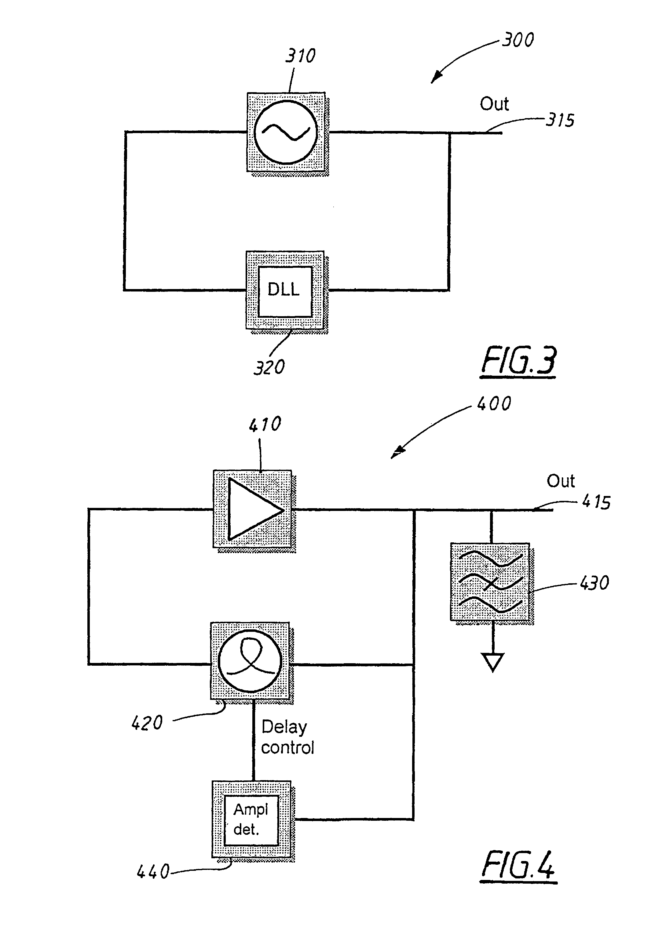
[0031]As can be seen from FIG. 3, the oscillating element 310 of the embodiment 300 is not an amplifier, but rather an oscillator, for example a Voltage Controlled Oscillator, commonly abbreviated as VCO. In oscillator circuits based on the principle of self-injection locked oscillators, the phase noise of the oscillator circuit also becomes lower in proportion to the delay of the delay circuit employed, and it is of importance in this kind of oscillator circuits as well to control the phase of the feedback signal.

[0032]The output signal 315 from the oscillating element, the VCO 310 is used as output signal from the entire oscillating circuit 300 and, according to the invention, fed back to the VCO via a tuneable delay element, a DLL 320.

[0033]Since the function of the DLL has been touched upon earlier in this text, it will not be elaborated upon further here. However, the loop bandwidth of the DLL should be rather small, in order to ensure that the DLL doesn't regulate on phase noi...


PUM


Abstract

The invention discloses an oscillator circuit (100, 200, 300, 400), comprising an oscillating element (110, 210, 310, 410) and output means (115, 215, 315, 415) for outputting an oscillation frequency from the oscillating circuit. The circuit further comprises a signal delay means (120, 220, 320, 420) which is arranged in series with the oscillating element and feeds the output signal back to the oscillating element. The delay means is (120, 220, 320, 420) tuneable with respect to the delay it provides. The oscillating element can be an amplifier or a VCO, and the delay means can be a Delay Locked Loop or a tuneable delay line, depending on the embodiment of the invention.

Description

[0001]This application is the US national phase of international application PCT / SE2003 / 001917 filed 10 Dec. 2003, which designated the U.S., the entire contents of which are hereby incorporated by reference.TECHNICAL FIELD[0002]The present invention relates to an oscillator circuit with delay means. The invention addresses, inter alia, problems with obtaining the correct delay in the delay means.BACKGROUND ART[0003]Time or phase delays in electrical signals are often used in various applications, such as, for example, electrically controlled antennas, phase shifters and frequency tuning of resonators in filters and oscillators.[0004]For use in oscillator circuits, various principles using delay lines have been disclosed. A problem with delay lines in oscillators is that the delay provided by the delay lines must be very precise, due to the fact that the delay is optimal for a single frequency only, which thus makes the circuit sensitive, and necessitates a high degree of precision ...

Claims


Application Information

Patent Timeline
Patent Type & Authority Patents(United States)
IPC IPC(8): H03B27/00H03B5/24H03L7/081
CPCH03B5/24H03L7/0812H03L7/0816H03B5/00
Inventor JACOBSSON, HARALDGEVORGIAN, SPARTAKLEWIN, THOMAS
Owner HIGHBRIDGE PRINCIPAL STRATEGIES LLC AS COLLATERAL AGENT
Why Eureka
Try Eureka