Backpack

a backpack and backpack technology, applied in the field of backpacks, can solve the problems of user's misfortune, inconvenience for users with backpacks while using their arms, and inconvenient ex-batteries replacement,

Active Publication Date: 2008-05-06
HANCOM LIFECARE INC
View PDF7 Cites 20 Cited by
  • Summary
  • Abstract
  • Description
  • Claims
  • Application Information

AI Technical Summary

Benefits of technology

[0022]Accordingly, the present invention has been made keeping in mind the above problems occurring in the prior art, and an object of the present invention is to provide a backpack in which both a waist belt and harnesses move independently from a backboard, the harnesses move independently from the waist belt, and inclination angles (movable angles in upward, downward, forward and backward directions) of both the waist belt and the harnesses worn on a user can be freely adjusted as desired.
[0023]Another object of the present invention is to provide a backpack in which the location of a battery casing is changed from a conventional location, thus allowing for easy changing of batteries, and which is produced without a conventional process of attaching a support frame to the backboard, and in which the structure of the support frame is changed to prevent the support frame from catching on protruding objects.Technical Solution
[0026]Thus, the waist belt and the harnesses of the backpack are operated around the hinge shaft separately from the backboard, and furthermore, the waist belt and the harnesses are operated separately, so that the user works freely without being restricted or stressed by the waist belt or the harnesses.
[0029]The rotary unit may further comprise: a rotating angle control means for controlling the rotating angle of the waist protector. The rotating control means may comprise: the hinge shaft cover having a rectangular shape and mounted to the end of the hinge shaft; and inclined protrusions formed on the backboard on opposite sides of the hinge shaft cover to stop the hinge shaft cover during rotation of the hinge shaft cover, thus causing the waist protector to rotate within an angular range determined by an inclination angle of the protrusions.
[0033]The backpack may further comprise: an anti-friction member having a ring shape and fitted over the guide protrusion of the lift guide at a position between the guide boss and the lift guide, thus preventing direct contact of the guide boss with the lift guide.

Problems solved by technology

Particularly, when the user of the backpack is a fireman and falls due to the change in the center of gravity of the compressed-air cylinder 50 on the scene of a fire, the user may meet with misfortune.
Thus, the user with the backpack is inconvenienced while using his / her arms due to the restriction caused by both the back belt 21 and the harnesses 30.
Thus, it is inconvenient to ex change the batteries for new ones and excessive time must be consumed while changing the batteries.
Also, the support frame 15 is made of iron, resulting in an increase in the weight of the backpack.
Furthermore, due to the support frame 15 which may easily catch on protruding objects, the fireman may have difficulty quickly escaping from danger at the scene of a fire.
The consumption of excessive time during backpack production process results in a reduced quantity of backpacks being produced.

Method used


Image

  • Backpack
  • Backpack
  • Backpack

Examples


first embodiment

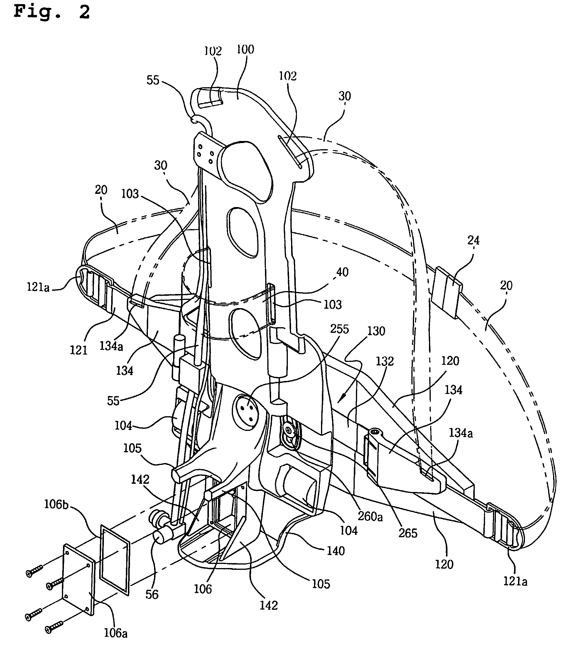
[0057]In the accompanying drawings, FIG. 2 is a perspective view showing a backpack according to the present invention. FIG. 3 is an exploded perspective view showing the construction of the backpack of FIG. 2. FIG. 4 is a front view showing a backboard shown in FIG. 2.

[0058]FIG. 5 is a front view of a harness support shown in FIG. 2. FIG. 6 is a front view of a waist protector shown in FIG. 2. FIG. 7 is a sectional view taken along the line A-A′ of FIG. 6, showing a part of the waist protector of FIG. 2.

[0059]FIG. 8 is a front view showing the operation of the waist protector of FIG. 2. FIG. 9 is a front view showing the operation of the harness support of FIG. 2. FIG. 10 is a side view showing the state of the backpack according to the first embodiment of the present invention in use.

[0060]As shown in FIGS. 2 and 3, the backpack according to the first embodiment of the present invention includes a backboard 100. Harness locking holes 102 are formed on an upper portion of the backb...

second embodiment

[0112]FIG. 11 is a perspective view showing the backpack according to the present invention. FIG. 12 is an exploded perspective view of the backpack of FIG. 11. FIG. 13 is a front view of a backboard shown in FIG. 11.

[0113]In addition, FIG. 14 is a front view of a harness support shown in FIG. 11. FIG. 15 is a front view of a waist protector shown in FIG. 11. FIG. 16 is a sectional view taken along the line B-B′ of FIG. 15. FIG. 17 is an exploded perspective view of a lift assembly shown in FIG. 15. FIG. 18 is a longitudinal sectional view showing a coupled state of the backboard, harness support and waist protector shown in FIG. 11.

[0114]Furthermore, FIG. 19 is a view showing the state of the harness support of FIG. 11 in use. FIG. 20 is a view showing the state of the waist protector of FIG. 11 in a rotating motion. FIG. 21 is a view showing the state of the waist protector of FIG. 11 in a rising and falling motion. FIG. 22 is a view showing the state of the waist protector of FIG...


PUM


Abstract

A backpack for back-mounting a compressed-air cylinder, fastened to the backpack by a cylinder fastening belt, when a user wears harnesses and a waist belt. The backpack inlcudes a backboard (100) having support hooks (105) to support the compressed-air cylinder (50); a harness support (130) for the harnesses (30) coupled to the backboard (100) so as to rotate upwards and downwards around the center; a waist protector (120) coupled to the backboard (100) in the back of the harness support (130) so as to cover and protect the back of the user's waist; and a rotary unit for rotatably supporting both the harness support (130) and the waist protector (120) on the backboard (100). The waist protector and the harness support move separately from the backboard by the rotary unit, thus allowing the user to work without stressed by the waist belt or the harnesses.

Description

TECHNICAL FIELD[0001]The present invention relates, in general, to a backpack used for back-mounting something and, more particularly, to a backpack used for conveniently back-mounting a compressed-air cylinder.BACKGROUND ART[0002]Generally, backpacks used for back-mounting compressed-air cylinders include a flat backboard, with shoulder harnesses, a waist belt and a cylinder fastening belt integrated with the backboard into a single structure. To back-mount a compressed-air cylinder using such a backpack, the compressed-air cylinder is fastened to the backboard using the cylinder fastening belt, and thereafter, a user back-mounts the compressed-air cylinder by wearing both the shoulder harnesses on his / her shoulders and the waist belt around his / her waist.[0003]As shown in FIG. 1, a conventional backpack comprises a backboard 10 to which a compressed-air cylinder 50 is fastened in a vertical position, with shoulder harnesses 30 and a waist belt 20 having a buckle 24 all being coupl...

Claims


Application Information

Patent Timeline
Patent Type & Authority Patents(United States)
IPC IPC(8): B63C11/02A45F3/04A45F3/08A62B9/04
CPCA45F3/047A45F3/08A62B9/04
Inventor KIM, JONG-KEE
Owner HANCOM LIFECARE INC
Why Eureka
Try Eureka