Engine generator

a generator and engine technology, applied in the field of engine generators, can solve the problems of increasing costs, not easily stackable, and the description of engine generators, and achieve the effect of making the most of the spa

Active Publication Date: 2008-10-07
YAMAHA MOTOR POWER PROD KK
View PDF29 Cites 14 Cited by
  • Summary
  • Abstract
  • Description
  • Claims
  • Application Information

AI Technical Summary

Benefits of technology

[0008]An aspect of at least one of the embodiments disclosed herein includes the realization that, in some applications, users attempt to stack a number of engine generators vertically for storage in order to make the most of the space at a particular facility. For example, distributors of such engine generators may stack such generators to use the existing space most efficiently.
[0009]The engine generator described in JP-A-Hei 8-223856, however, is not easily stackable. Thus, to vertically stack the engine generators, users often use a sheets of plywood placed between the engine generators to create a vertical stack. Alternatively, some manufacturers offer a stacking kit with separate members configured to vertically stack engine generators. This results in a problem that stacking work of the engine generators becomes troublesome, and specific stacking members are required for each generator design, thereby increasing costs.

Problems solved by technology

The engine generator described in JP-A-Hei 8-223856, however, is not easily stackable.
This results in a problem that stacking work of the engine generators becomes troublesome, and specific stacking members are required for each generator design, thereby increasing costs.

Method used


Image

  • Engine generator
  • Engine generator
  • Engine generator

Examples


Embodiment Construction

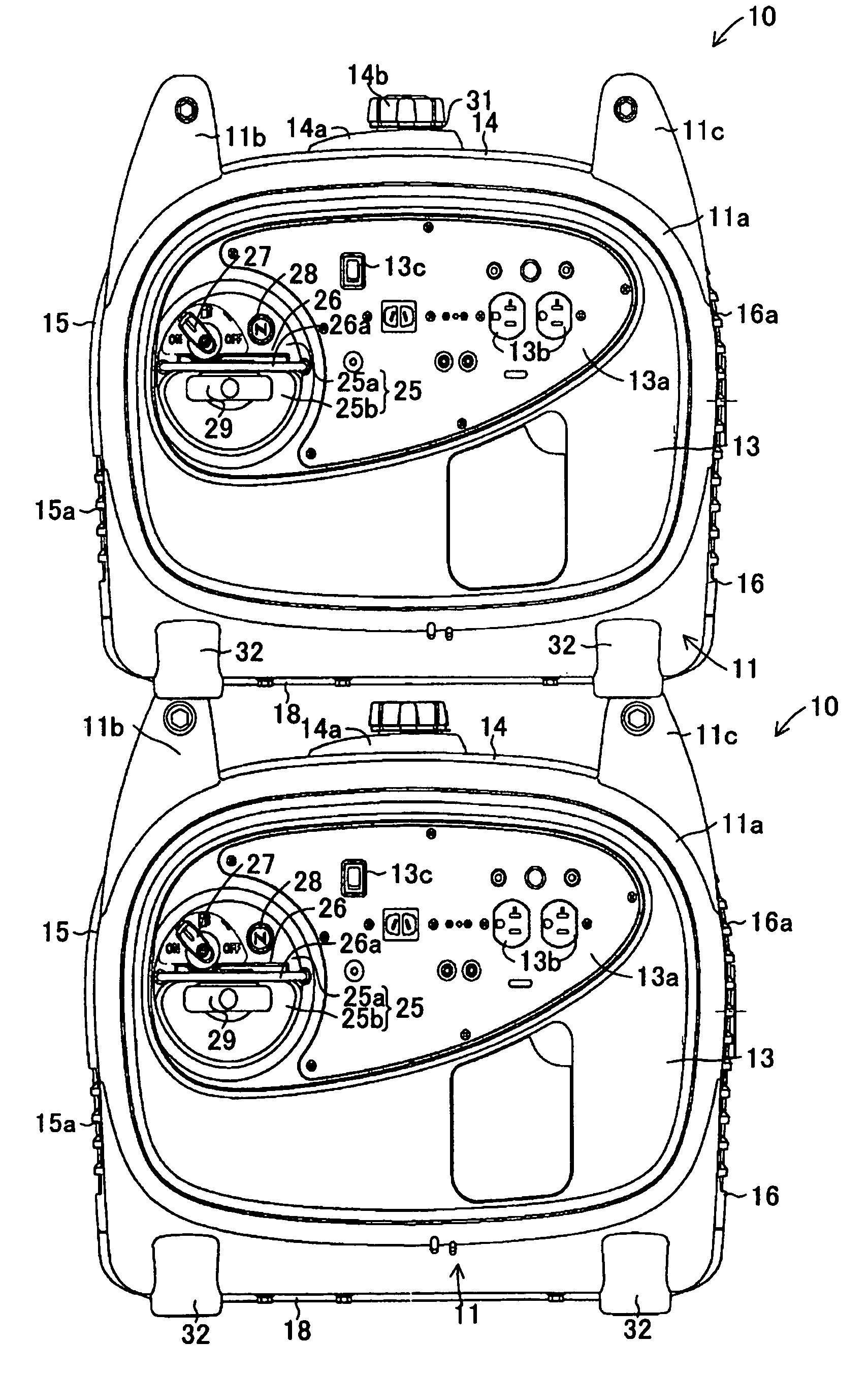
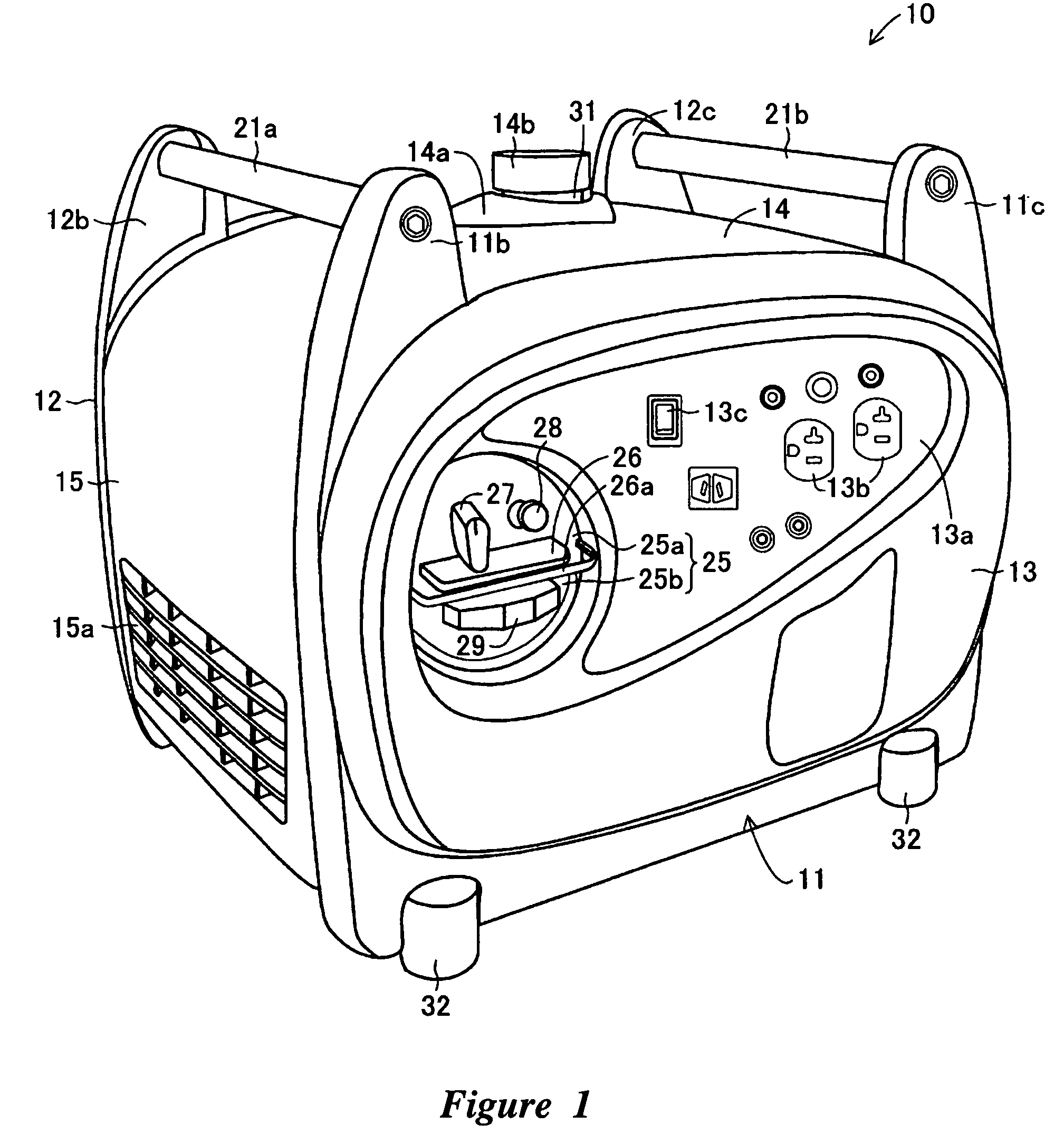
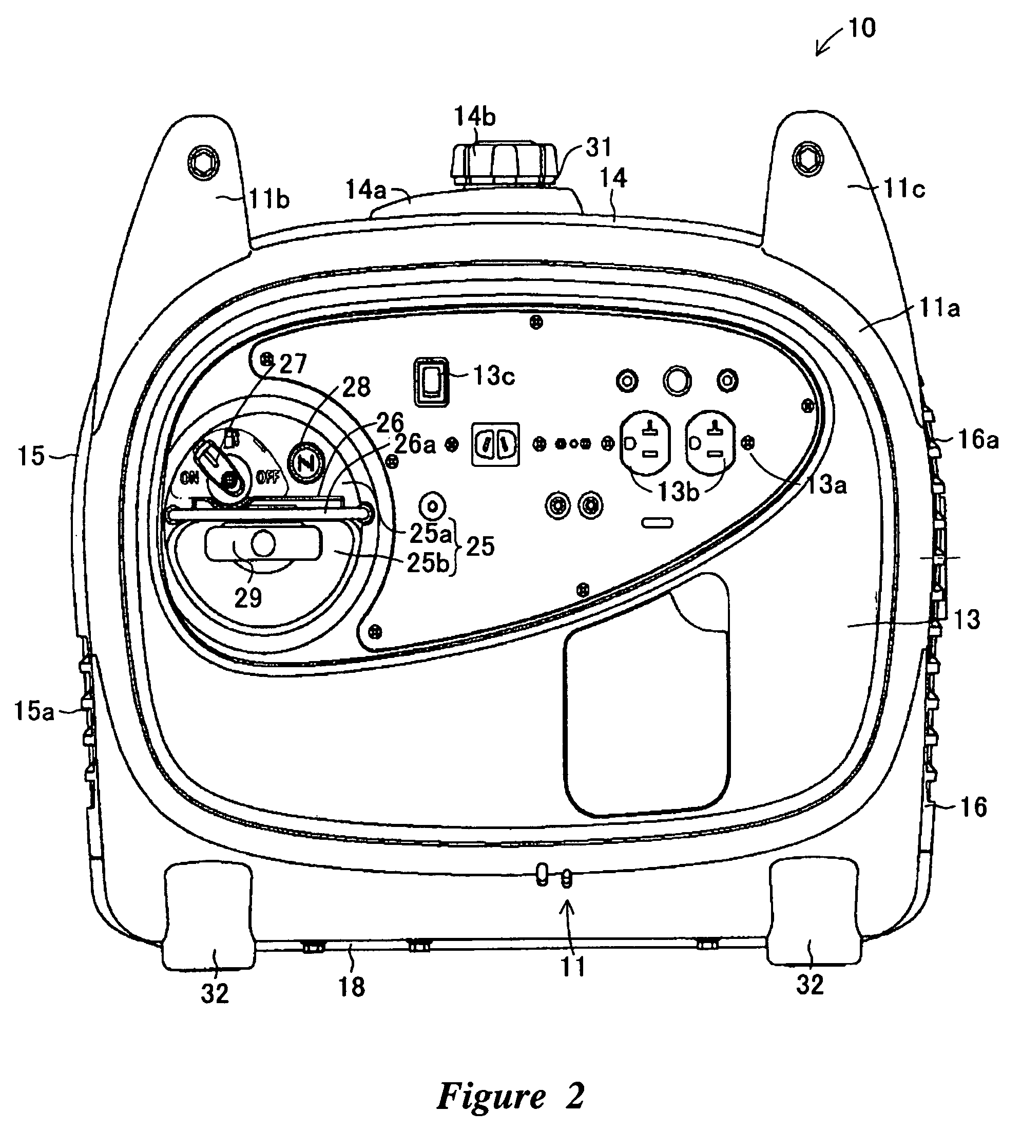
[0027]An engine generator having handle and mount arrangements in accordance with various embodiments of the present invention is described below with reference to drawings. The handle and mount arrangements are described in the context of an engine generator because they have particular utility in this context. However, the handle and mount arrangement disclosed herein can be used in other contexts, such as, for example, any device that can be both carried and stacked.

[0028]With reference to FIGS. 1 through 5, the outer surface of the engine generator 10 can be formed in a rounded, generally box shape. The generator can also include a pair of front and rear frames 11, 12 spaced apart from each other in the forward and rearward directions. A front panel 13 and a rear panel 17 can be located within the front frame 11 and the rear frame 12, respectively. A top panel 14, an intake cover 15, an exhaust cover 16 and a bottom panel 18 can be located between the front frame 11 and the rear...


PUM


Abstract

Mounts can be provided at the four corners of a bottom portion of an engine generator. Projections for mounting handles can be provided at a top portion of the engine generator in vertical alignment above the mounts. The bottom face of each mount can be formed with a fitting groove having an open end. Fitting the projections in the fitting grooves allows stacking plural engine generators. The mount can be constituted with a bottom portion, a side portion, and a reinforcing metal fitting. The projections can be disposed on a front frame and a rear frame, respectively, each formed in one body. The mounts can also be attached to the front frame and the rear frame.

Description

PRIORITY INFORMATION[0001]This application is based on and claims priority under 35 U.S.C. §119 to Japanese Patent Application. No. 2004-362257, filed on Dec. 15, 2004, the entire contents of which is hereby expressly incorporated by reference.BACKGROUND OF THE INVENTIONS[0002]1. Field of the Inventions[0003]The present inventions relate to engine generators having handles for carrying the associated engine generator and having mounts for supporting the engine generator.[0004]2. Description of the Related Art[0005]Engine generators having an engine for driving a generator to generate electric power have long been known. Some known engine generator designs include handles for carrying the engine generator, and mounts for supporting the engine generator. For example, Japanese Patent Document No JP-A-Hei 8-223856 illustrates such a generator. This generator has the top face provided with a handle which is bent in a squared U shape. The bottom face is formed with four support projection...

Claims


Application Information

Patent Timeline
Patent Type & Authority Patents(United States)
IPC IPC(8): F02B77/00H02K5/00
CPCF02B63/04F02B63/048H02K5/00H02K7/1815
Inventor YAMAMOTO, MASANOBUSUGIYAMA, TAKAHIDE
Owner YAMAHA MOTOR POWER PROD KK
Why Eureka
Try Eureka