Coupler with waveguide transition for an antenna in a radar-based level measurement system

a technology of waveguide transition and antenna, applied in the direction of liquid/fluent solid measurement, instruments, using reradiation, etc., can solve problems such as affecting the performance of radar

Active Publication Date: 2008-11-18
SIEMENS AG
View PDF38 Cites 256 Cited by
  • Summary
  • Abstract
  • Description
  • Claims
  • Application Information

AI Technical Summary

Problems solved by technology

If there are losses or signal degradation in the transition between the coaxial waveguide and the antenna waveguide, then radar performance is affected.

Method used


Image

  • Coupler with waveguide transition for an antenna in a radar-based level measurement system
  • Coupler with waveguide transition for an antenna in a radar-based level measurement system
  • Coupler with waveguide transition for an antenna in a radar-based level measurement system

Examples


Embodiment Construction

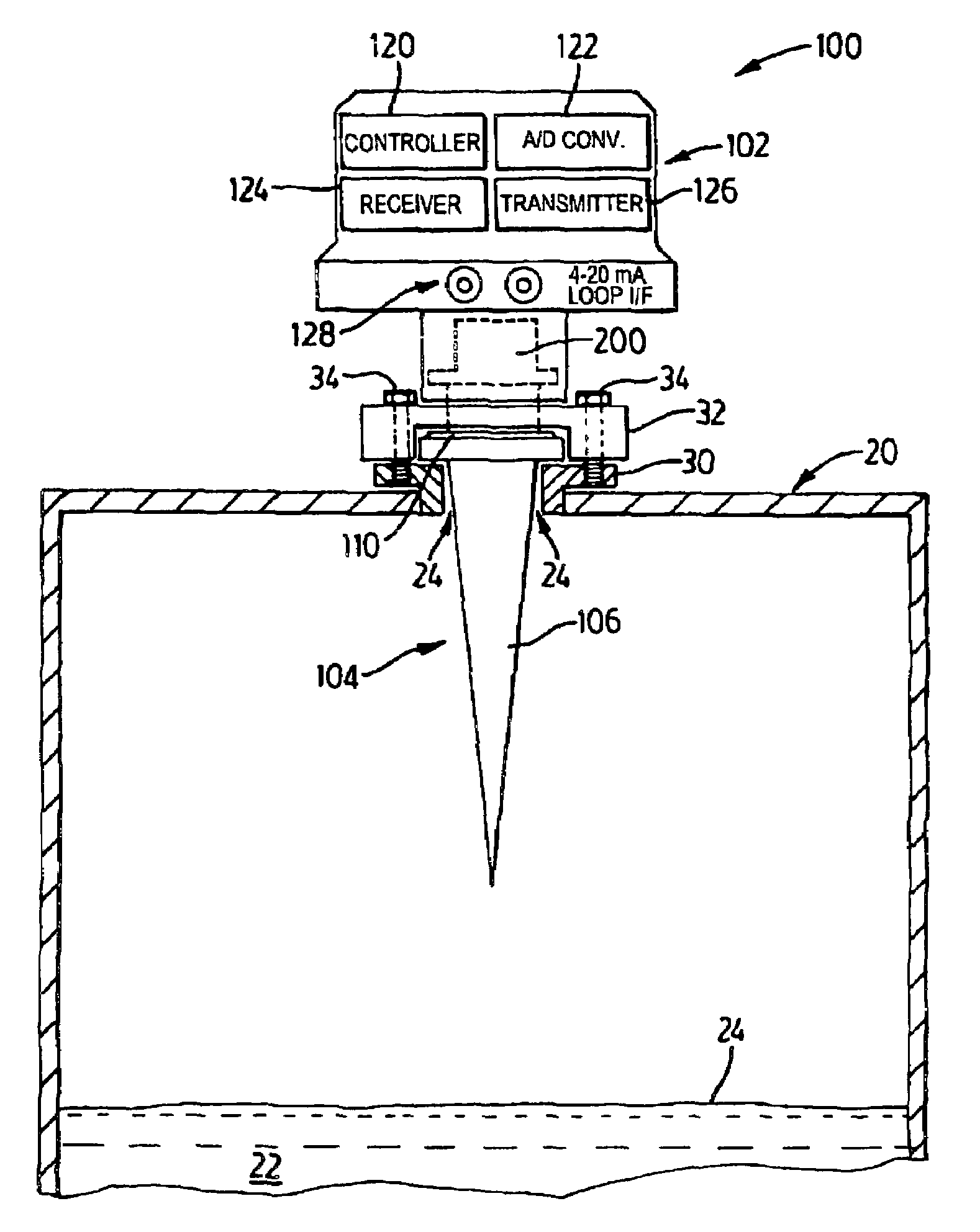
[0031]Reference is first made to FIG. 1 which shows in diagrammatic form a radar-based or a microwave-based level measurement apparatus 100 with an antenna having a coupler assembly or transition structure in accordance with the present invention.

[0032]As shown in FIG. 1, the level measurement apparatus 100 is mounted on top of a container or vessel 20 which holds a material 22, e.g. liquid, slurry or solid. The level measurement apparatus 100 functions to determine the level of the material 22 held in the vessel 20. The level of the material 20 is defined by a top surface, and denoted by reference 23, which provides a reflective surface for reflecting electromagnetic waves or energy pulses. The vessel or container 20 has an opening 24 which may include a flange 30. The level measurement apparatus 100 is attached or clamped to the opening 24 using suitable fasteners as will be familiar to those skilled in the art.

[0033]The level measurement apparatus 100 comprises a housing member o...


PUM


Abstract

A mechanism for coupling a coaxial waveguide to another waveguide. The mechanism includes a lower or matching waveguide and an impedance transformer. A coaxial port couples the coaxial waveguide to the matching waveguide. The matching waveguide has a waveguide impedance which is close to the impedance of the coaxial waveguide. This arrangement allows matching between the coaxial waveguide and the matching waveguide over a wider frequency band. The impedance transformer couples the matching waveguide to the other waveguide. The impedance transformer comprises a single-stage, double-stage, or multi-stage transformer. The mechanism is suitable for coupling an antenna to a coaxial cable interface in a radar or microwave based level measurement or time of flight ranging systems.

Description

FIELD OF THE INVENTION[0001]The present invention relates radar-based level measurement systems, and more particularly to a coupler with a waveguide transition mechanism suitable for rod antenna and horn antenna applications, and other waveguide-based antennas such as slotted waveguides.BACKGROUND OF THE INVENTION[0002]Time of flight ranging systems find use in level measurements applications, and referred to as level measurement systems. Level measurement systems determine the distance to a reflective surface (i.e. reflector) by measuring how long after transmission energy, an echo is received. Such systems may utilize ultrasonic pulses, pulse radar signals, or other microwave energy signals.[0003]Pulse radar and microwave-based level measurement systems are typically preferred in applications where the atmosphere in the container or vessel is subject to large temperature changes, high humidity, dust and other types of conditions which can affect propagation. To provide a sufficien...

Claims


Application Information

Patent Timeline
Patent Type & Authority Patents(United States)
IPC IPC(8): H03H7/38G01S13/08
CPCG01F23/284H01P5/103G01S13/88
Inventor DUIVENVOORDEN, JOHANNES THEODORUS CORNELIS
Owner SIEMENS AG
Why Eureka
Try Eureka