Hub unit for use in electrically movable wheels and vehicle comprising the hub unit

a technology for electrically moving wheels and hub units, which is applied in the direction of electric devices, cycle equipment, optical signals, etc., can solve the problems of increasing the weight not being able to effectively radiate heat, and increasing the cost of the cooling liquid, so as to prevent the motor from overheating and suppress the overheating of the windings. , the effect of automatic and efficient cooling

Inactive Publication Date: 2009-01-06
SANYO ELECTRIC CO LTD
View PDF26 Cites 25 Cited by
  • Summary
  • Abstract
  • Description
  • Claims
  • Application Information

AI Technical Summary

Benefits of technology

[0013]According to the present invention, the motor can be automatically and efficiently cooled with the air admitted into the hub from outside with the rotation of the hub. This reliably prevents the motor from overheating.
[0014]The cooling means thus provided eliminates the need for a coolant conventionally enclosed in the hub for suppressing the overheating of the windings. The motor housing need not be provided with a cylindrical wall, while there is no need for the time and labor required for enclosing the coolant in the hub. The hub unit can therefore be fabricated at a reduced cost. The removal of the cylindrical wall and the coolant results in a corresponding weight reduction, while the absence of the cylindrical wall gives a correspondingly greater outside diameter to the stator, whereby increased torque is made available.

Problems solved by technology

With the construction disclosed in the above patent publication, however, the stator is hermetically enclosed in a motor housing and therefore is not allowed to radiate heat effectively.
In the case where the coolant is enclosed in the hub, there is a need to provide a measure for preventing the leakage of the coolant to result in a cost increase.
The provision of the coolant entails a corresponding increase in weight.

Method used


Image

  • Hub unit for use in electrically movable wheels and vehicle comprising the hub unit
  • Hub unit for use in electrically movable wheels and vehicle comprising the hub unit
  • Hub unit for use in electrically movable wheels and vehicle comprising the hub unit

Examples


Embodiment Construction

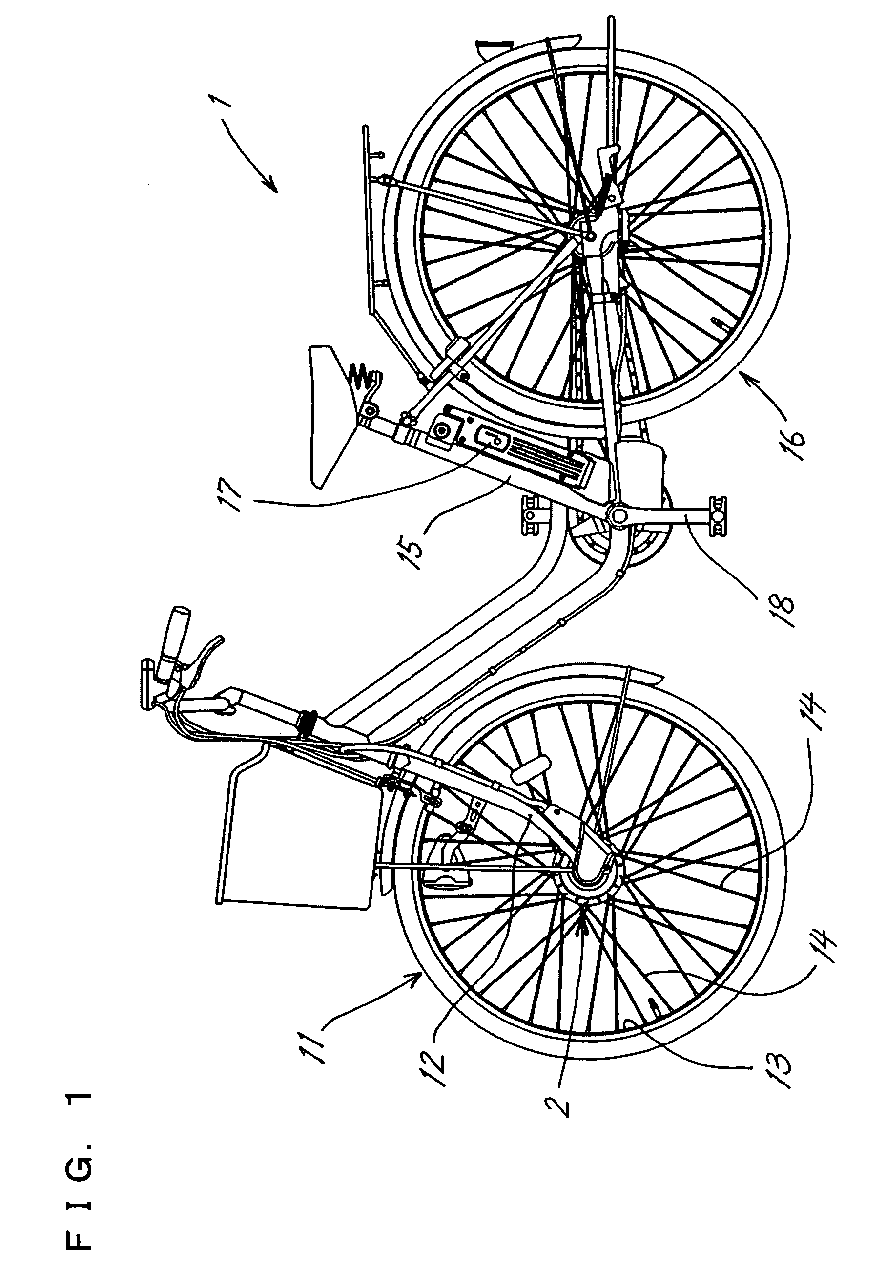
[0020]FIG. 1 shows an example of electrically assisted bicycle 1 having a hub unit 2 of the present invention.

[0021]A hub unit 2 is attached to the lower end of a front fork 12 of the bicycle 1, and the hub unit 2 and the rim 13 of a front wheel 11 are interconnected by spokes 14, 14.

[0022]A battery 17 is mounted on the bicycle between a seat post 15 and a rear wheel 16. A sensor (not shown) is provided on a suitable portion on which the pedaling force of the pedals 18 acts for energizing a motor 9 of the hub unit 2 by the battery 17 when the load on the pedals reaches a predetermined value.

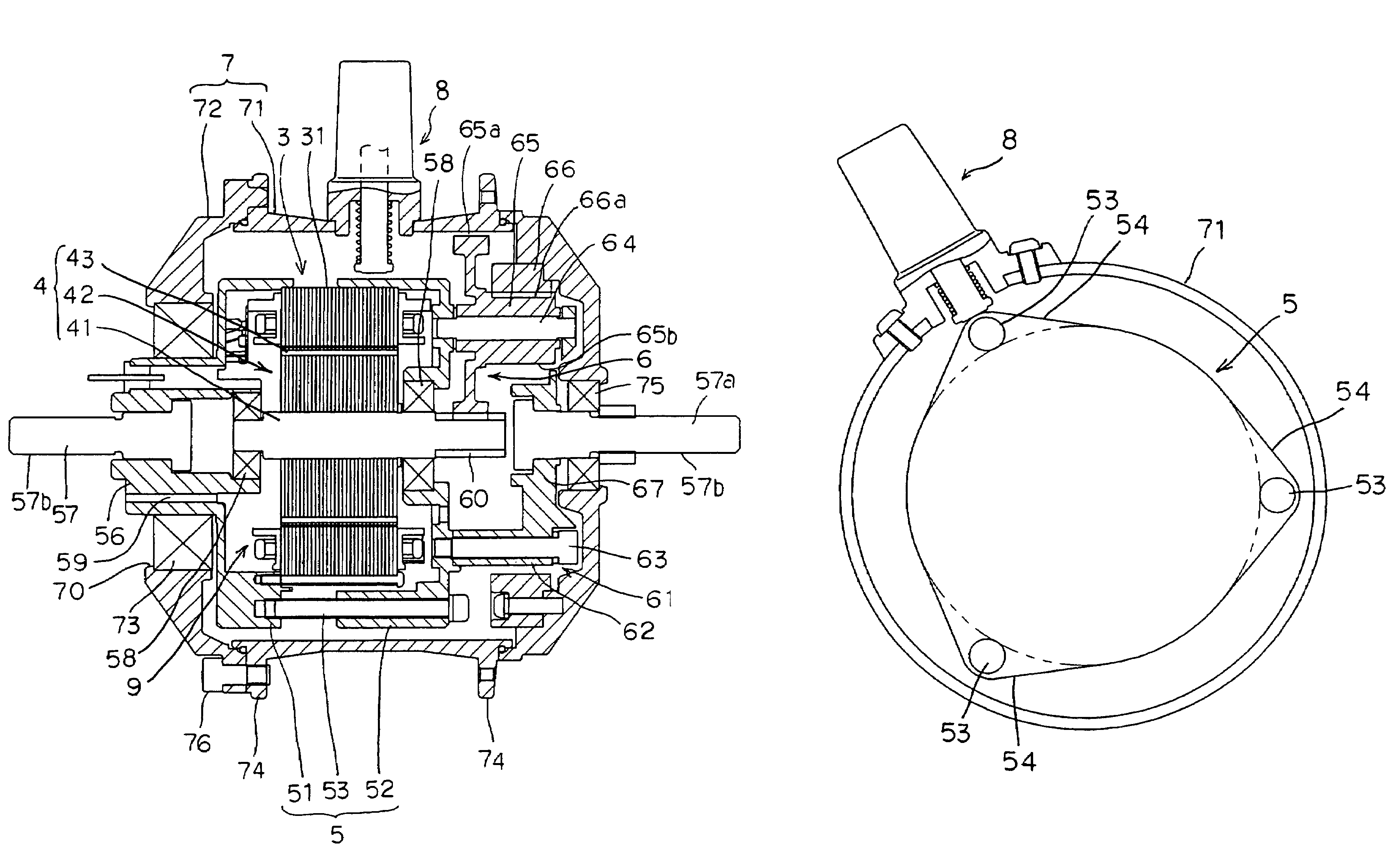
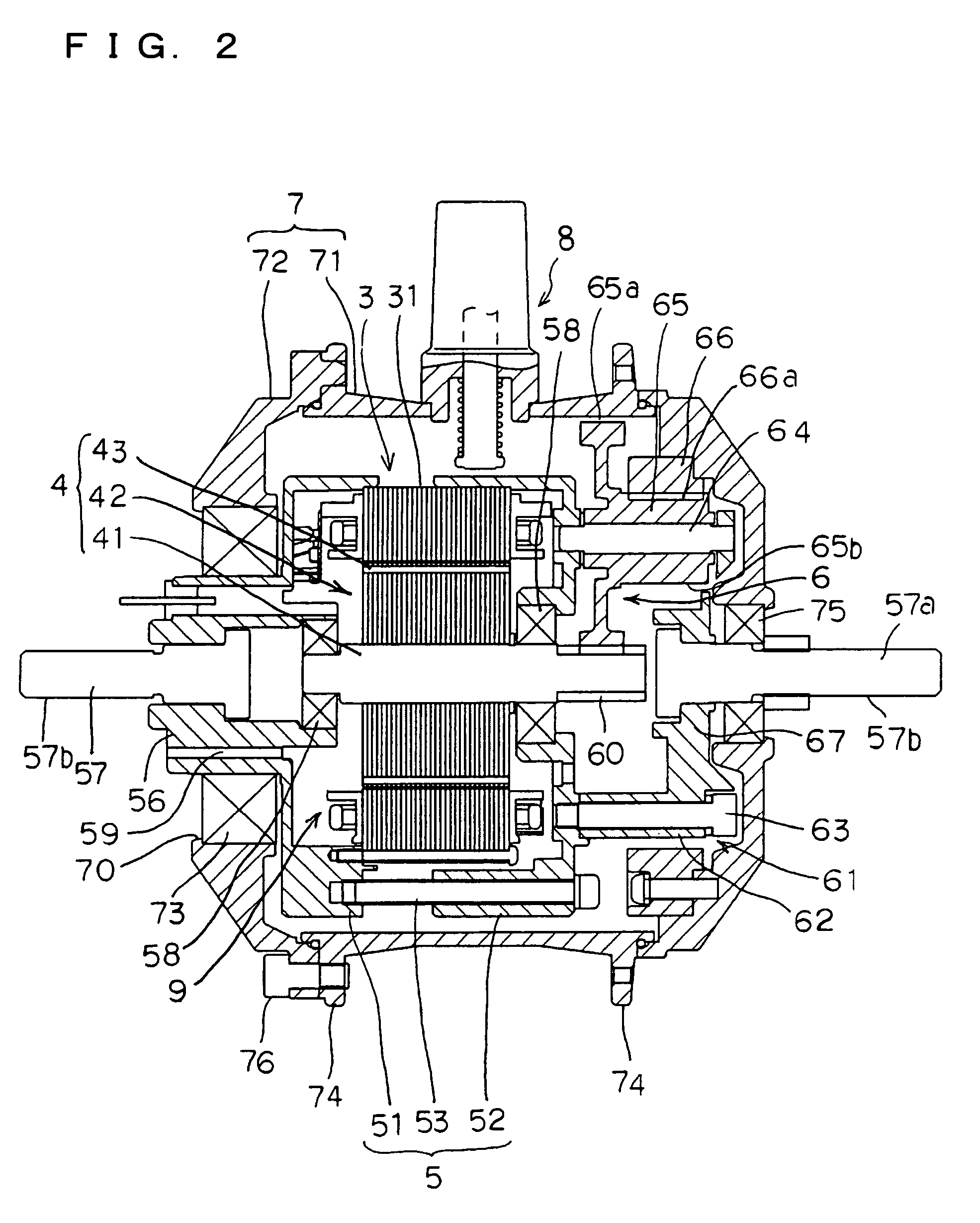
[0023]The hub unit 2, which basically has the same construction as those of the prior art, has the above-mentioned motor 9 which comprises a stator 3 and a rotor 4, a hub 7 enclosing the motor 9 therein and rotatingly driven by the rotation of the motor 9, and a fixing support shaft 57 projecting in a fixed state from a motor housing 5 in alignment with the axis of rotation of the hub 7 and exten...


PUM


Abstract

A hub unit for use in electrically assisted bicycles is improved in an effect to cool a motor incorporated in the unit. The hub unit has a motor 9 comprising a stator 3 and a rotor 4, and a hub 7 enclosing the motor 9 therein and rotatingly drivable by the rotation of the rotor 4. The unit has a pump 8 for discharging air from inside the hub 7 with the rotation of the hub 7. The air is discharged from inside the hub 7 by the operation of the pump 8, whereby air is admitted into the hub 7 from outside through an air port 59 formed in the hub 7 and is supplied to the motor 9 to cool the motor 9 and reliably prevent the motor from overheating.

Description

FIELD OF THE INVENTION[0001]The present invention relates to hub units for use in electrically movable wheels, and to electrically assisted bicycles, wheelchairs and like vehicles comprising the hub unit.BACKGROUND OF THE INVENTION[0002]As disclosed, for example, in JP-A No. 2002-514550, electrically assisted bicycles are known which have a hub unit provided on the hub of a wheel of the bicycle and incorporating a motor or the like therein, such that the motor is driven when the pedals are subjected to a load not lower than a predetermined value, permitting the rider to run up a slope with ease.[0003]The hub unit becomes heated when the motor is energized. When overheated, the motor can not be rotated with high torque, so that there is a need to provide a contrivance to release the heat from the motor.[0004]With the construction disclosed in the above patent publication, however, the stator is hermetically enclosed in a motor housing and therefore is not allowed to radiate heat effe...

Claims


Application Information

Patent Timeline
Patent Type & Authority Patents(United States)
IPC IPC(8): B60K1/00B62M6/65B62M7/12
CPCB62M6/65B62M7/12B60L3/0061B60L11/007B60L11/1877B60L15/20B62M6/80Y02T10/641B60L2200/12B60L2220/14B60L2220/44B60L2240/36B60L2240/425B60L2250/16B60L2250/26B60L2220/50Y02T10/7005Y02T10/705Y02T10/7275Y02T10/642Y02T10/72B60L50/20B60L50/66Y02T10/64Y02T10/70
Inventor TOMOSHIGE, KAZUHIROADACHI, RYOHEI
Owner SANYO ELECTRIC CO LTD
Why Eureka
Try Eureka