Plasma display panel

a technology of display panel and plasma, which is applied in the direction of identification means, electrical apparatus casings/cabinets/drawers, instruments, etc., can solve the problems of lowering productivity and bracket damage, and achieve the effects of reducing manufacturing costs, increasing operation efficiency, and enhancing rigidity of chassis bases

Inactive Publication Date: 2009-02-17
SAMSUNG SDI CO LTD
View PDF33 Cites 4 Cited by
  • Summary
  • Abstract
  • Description
  • Claims
  • Application Information

AI Technical Summary

Benefits of technology

[0009]The present invention provides a plasma display panel that includes a chassis base and an associated reinforcing member disposed to impart strength and enhance the rigidity of the chassis base. The reinforcing member is integrally manufactured with the chassis base, thereby increasing operation efficiency, reducing manufacturing cost, and providing a lightweight chassis base.
[0010]According to an aspect of the present invention, there is provided a plasma display panel including a plasma display panel assembly for displaying various visual images, a chassis base coupled to the panel assembly for supporting the panel assembly, and a reinforcing member integrally formed in the chassis base so as to reinforce the rigidity of the chassis base. The reinforcing member may have a beading member that projects from a rear surface of the chassis base. An engagement hole may be formed in the reinforcing member to connectedly receive an external engagement member. A boss may be formed in the reinforcing member to accommodate engagement.
[0011]According to another aspect of the present invention, there is provided a plasma display panel including a plasma display panel assembly for displaying an image, a chassis base including a rib perforated by a plurality of openings, a circuit substrate coupled to the chassis base, and a reinforcing member integrally formed in the chassis base so as to reinforce the rigidity of the chassis base. The reinforcing member may have a beading member that projects from the rear surface of the chassis base. The circuit board may be mounted on the rib.

Problems solved by technology

In this case, additional processes are necessary to separately manufacture a chassis base and brackets, and to couple the brackets into the chassis base, thereby lowering productivity.
Moreover, if a chassis base and brackets are incompletely coupled to each other, brackets maybe damaged due to stress applied to their coupling components.

Method used


Image

  • Plasma display panel
  • Plasma display panel
  • Plasma display panel

Examples


Embodiment Construction

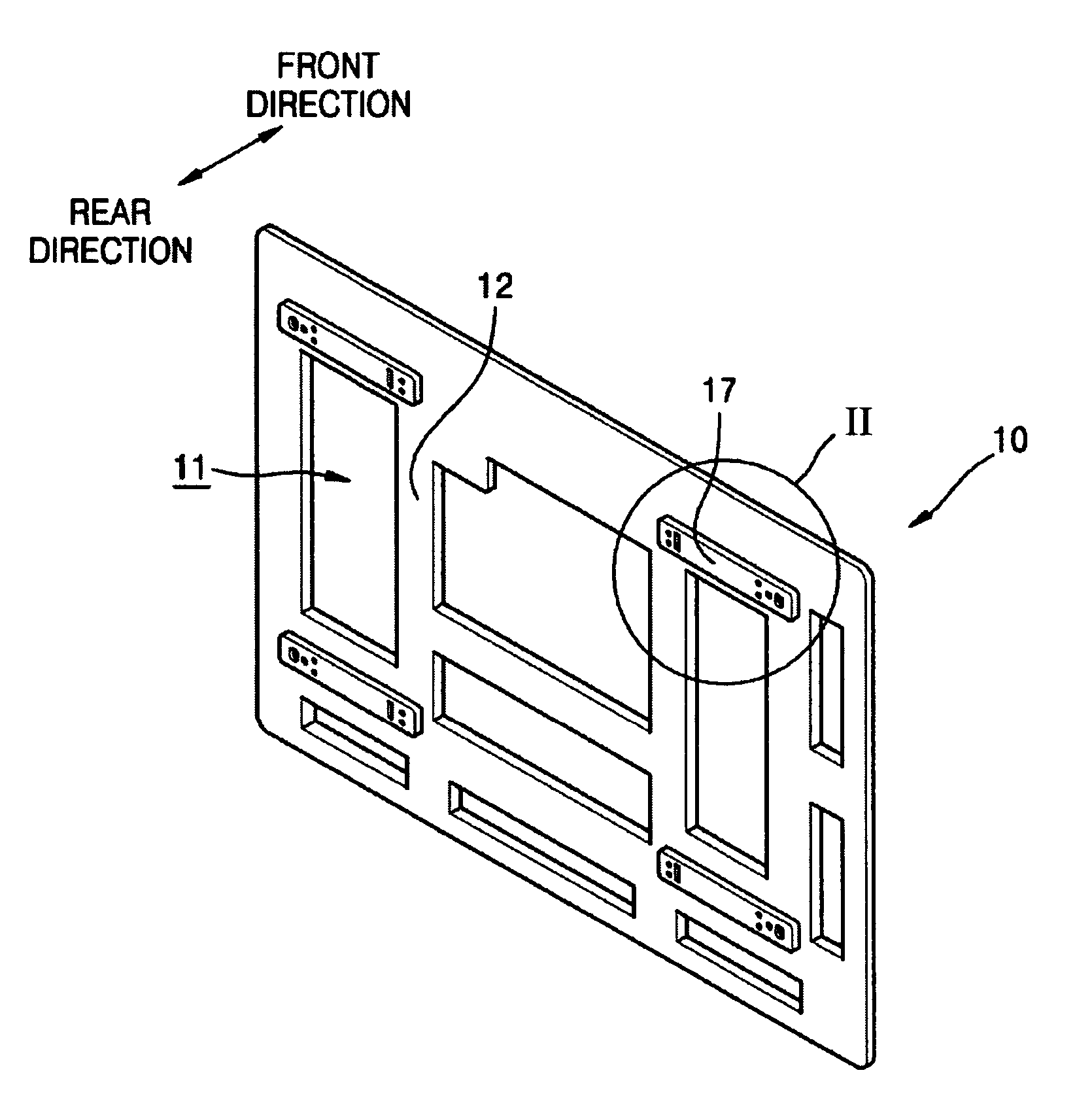
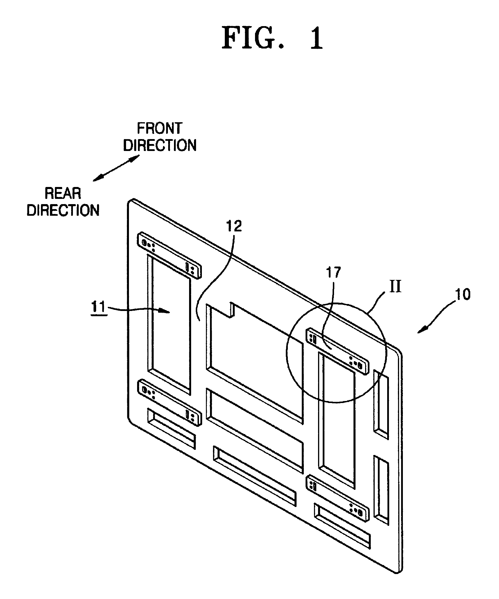
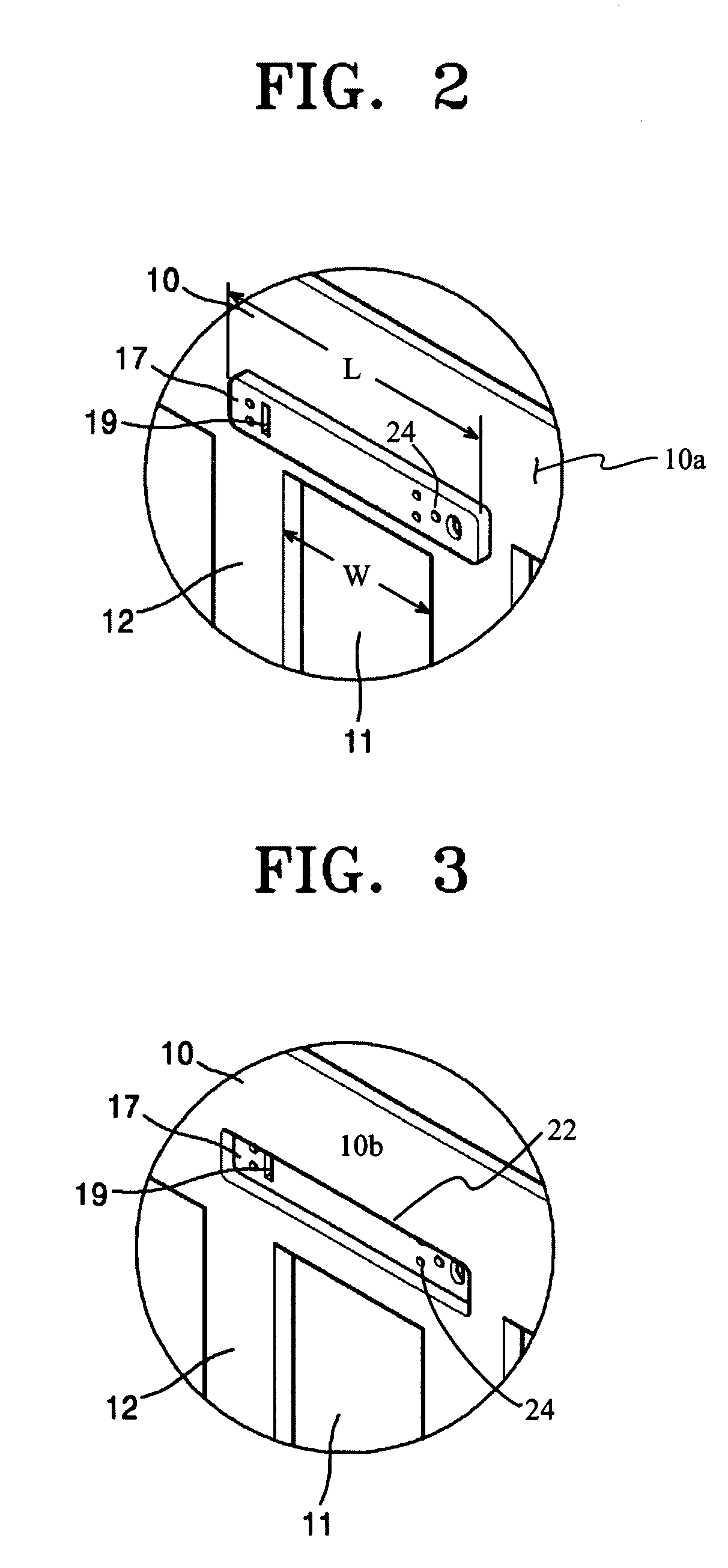
[0016]FIG. 1 is a perspective view of a chassis base 10 constructed as an embodiment of the present invention. Referring to FIG. 1, flat type chassis base 10 is perforated by a plurality of openings 11 having various sizes and shapes. Openings 11 are formed to correspond to the shape of a circuit substrate to be mounted on chassis base 10. The circuit substrate is coupled to openings 11. A portion of the circuit substrate may cover openings 11, or may be disposed inside openings 11. Rib 12 is formed between openings 11 and separates adjacent openings 11. A circuit substrate is mounted on rib 12 via a boss (not shown). While chassis base 10 can be made of aluminum, chassis base 10 is preferably made of plastic materials in order to assure a lightweight plasma display panel. Beading member 17 is coupled to chassis base 10. Beading member 17 functions as a reinforcing member that improves the rigidity of chassis base 10. Beading member 17 may be integrally formed with chassis base 10.

[...


PUM

PropertyMeasurementUnit
rigidityaaaaaaaaaa
lengthaaaaaaaaaa
stressaaaaaaaaaa

Abstract

A plasma display panel has a plasma display panel assembly for displaying an image, a chassis base coupled to the panel assembly and supporting the panel assembly, and a reinforcing member integrally formed in the chassis base so as to improve the rigidity of the chassis base. The reinforcing member is integrally manufactured with the chassis base. This structure provide improved operation efficiency and lower manufacturing cost, while maintaining the rigidity of the chassis base.

Description

CLAIM OF PRIORITY[0001]This application makes reference to, incorporates the same herein, and claims all benefits accruing under 35 U.S.C. § 119 from an application for PLASMA DISPLAY PANEL, earlier filed in the Korean Intellectual Property Office on the 4th of June 2005 and there duly assigned Serial No. 10-2005-0048116.BACKGROUND OF THE INVENTION[0002]1. Field of the Invention[0003]The present invention relates to a plasma display panel, and more particularly to a plasma display panel in which a chassis base and a reinforcing member are assembled together as a body.[0004]2. Description of the Related Art[0005]A plasma display panel (PDP) is typically constituted with a panel assembly including a front substrate and a rear substrate coupled to the front substrate. An adhesive tape is attached to the rear surface of a panel assembly, and a chassis base is coupled to the panel assembly through the adhesive tape. Heat-dissipating sheets maybe interposed between the panel assembly and ...

Claims


Application Information

Patent Timeline
Patent Type & Authority Patents(United States)
IPC IPC(8): H05K5/00G02F1/1333H01J17/26H05K7/00H01J17/49H01J5/48H01J5/50H01J61/28G09F9/00
CPCH05K5/02H01J11/20H01J11/34
Inventor KIM, YEUNG-KI
Owner SAMSUNG SDI CO LTD
Why Eureka
Try Eureka