Pneumatic device for cleaning ventilation ducts

a pneumatic device and ventilation duct technology, applied in the field of cleaning devices, can solve the problems of poor working environment and great labor strength, and achieve the effects of reducing the resistance of the pipe in the ventilation duct, compact structure, and reducing the number of operators

Inactive Publication Date: 2009-04-14
YU JIANG
View PDF3 Cites 0 Cited by
  • Summary
  • Abstract
  • Description
  • Claims
  • Application Information

AI Technical Summary

Benefits of technology

[0003]The technical problems the invention intends to solve are to overcome the disadvantages of the prior arts, and to provide a pneumatic device for cleaning ventilation ducts with small volume and simple structure, which is easy to use.
[0022]Advantages of the pneumatic device for cleaning ventilation ducts that the present invention related is: during the device cleaning the ventilation ducts, operator does not have to enter into the ducts. According to the principle of air motion of the guiding air hammer, cooperating with the guiding air hammer's direction controlling by slewing mechanism for the conduit, and the air-supply pipe's retracting and stretching by the retracting and driving device for air-supply pipe's manually operation or program composition, the dust on inner wall and each corner of ventilation ducts could be cleaned. Accompanying with the monitoring pick-up lens and the rolling wheel arranged under the slewing mechanism for the conduit, the retracting resistance of pipe in ventilation ducts is decreased. The brush in front of the guiding air hammer could be used to avoid the damage by the guiding air hammer to other devices inside the ventilation ducts. The design of the invention could be used for cleaning all ventilation ducts with polygonal section. According to the present invention, the pneumatic device for cleaning ventilation ducts has compact structure, has an advantage of automated operation, may clean any corner of the ventilation duct, decreased the number of operators, and reduced the labor strength of the operator greatly.

Problems solved by technology

For the ducts with large diameter, cleaning operator must enter the ducts to clean them, which results in great labor strength and bad working environment.

Method used


Image

  • Pneumatic device for cleaning ventilation ducts
  • Pneumatic device for cleaning ventilation ducts
  • Pneumatic device for cleaning ventilation ducts

Examples


Embodiment Construction

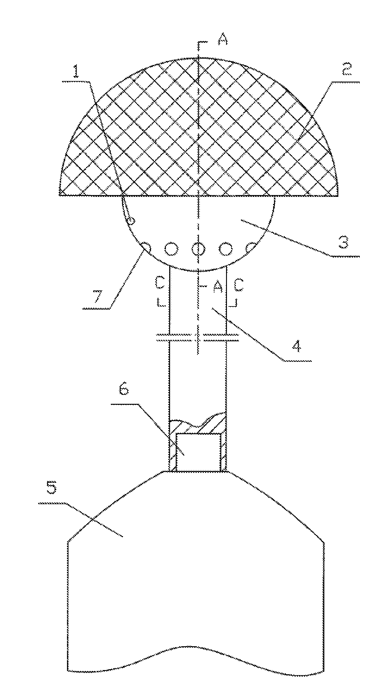
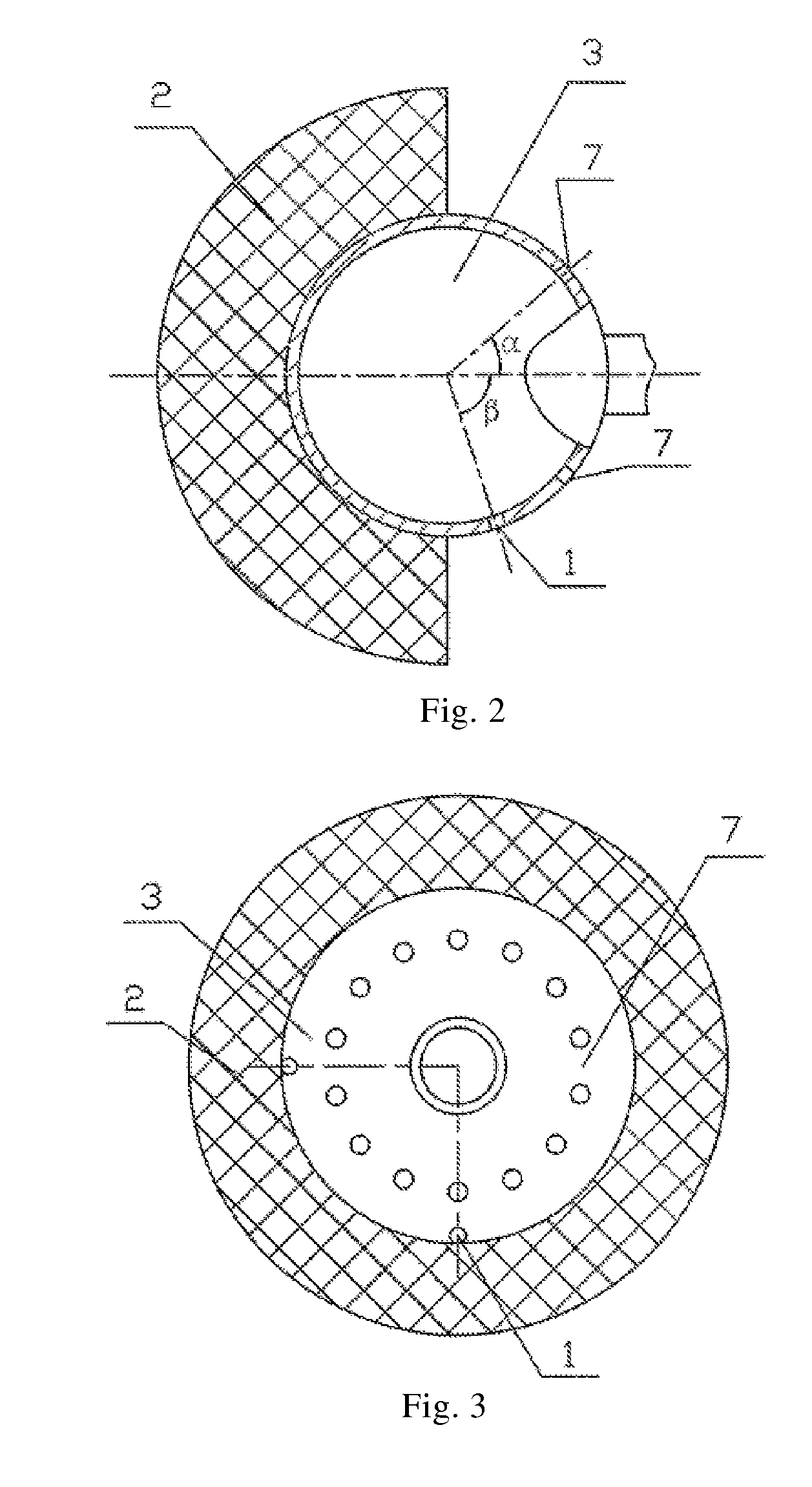
[0036]As shown in FIG. 1-FIG. 3, an embodiment of the pneumatic device for cleaning ventilation ducts of present invention comprises a guiding air hammer 3, a turning conduit 4, an air-supply pipe 16, and a slewing mechanism for the conduit 5. Said guiding air hammer 3 is a hollow spherical or hemispherical shape which connects to the turning conduit 4. The other end of said turning conduit 4 is arranged fixedly to the turning pipe 6 of the slewing mechanism for the conduit 5. Said air-supply pipe 16 is connected with air inlet pipe at the other end of the slewing mechanism for the conduit 5.

[0037]Jets of air for cleaning 7 and jets of air for guiding 1 are formed on the rear arc wall of said guiding air hammer 3, and said jets of air for cleaning 7 are several proportionally distributed centripetal holes, whose center lines make an angle of 35°-65° with the center line of guiding air hammer 3. Said jets of air for guiding 1 are two centripetal holes, whose center lines make an angl...


PUM


Abstract

The present application relates to a pneumatic device for cleaning ventilation ducts, which includes a guiding air hammer, a turning conduit, an air-supply pipe and a slewing mechanism for the conduit. The guiding air hammer has a hollow spherical or hemispherical shape and is connected to the turning conduit. A cleaning fumarole and a guiding fumarole are provided on the rear arc wall of the guiding air hammer. When in operation, the air-supply pipe stretching means retracts and stretches the air-supply pipe, which enables the guiding air hammer to clean out the dust on the inner walls and in the corners of a ventilation duct without the need of an operator entering the ventilation duct. The air-supply pipe stretching means may be controlled by manual operation or program composition. The device may be used for cleaning ventilation ducts with a polygonal section.

Description

FIELD OF THE INVENTION[0001]The present invention relates to a kind of cleaning device, and more specifically relates to a kind of pneumatic device for cleaning ventilation ducts.BACKGROUND OF THE INVENTION[0002]In the prior art, the method that manual operations accompany with high pressure air vehicles is generally used for cleaning the ducts, in which high pressure air is utilized for cleaning. For the ducts with large diameter, cleaning operator must enter the ducts to clean them, which results in great labor strength and bad working environment. The applicant has applied a Chinese patent application No. 200310113320.X on Nov. 14, 2003. The title of the patent application is cleaner for ventilation ducts, and the technique solution of this patent application is that the cleaning work was fulfilled by the cleaner for ventilation ducts carried by vehicles entering into the ducts, it has bigger volume and great loss of air force. The invention could only be used in horizontally arr...

Claims


Application Information

Patent Timeline
Patent Type & Authority Patents(United States)
IPC IPC(8): A47L25/00
CPCB08B9/047B08B9/0495B08B9/055
Inventor YU, JIANG
Owner YU JIANG
Why Eureka
Try Eureka