Compressed fluid system and related method

a foam system and compressed air technology, applied in brake systems, dental surgery, transportation and packaging, etc., can solve the problem of complete separation of pickup trucks, achieve the effects of preventing over-pressurization of tanks, reducing vehicle component cost, and saving engine energy

Active Publication Date: 2009-05-12
HME
View PDF15 Cites 21 Cited by
  • Summary
  • Abstract
  • Description
  • Claims
  • Application Information

AI Technical Summary

Benefits of technology

[0006]The aforementioned problems are overcome by the present invention which provides a compressed fluid system including a single compressor, driven by the engine of a firefighting vehicle, which generates a compressed fluid supply for operation of both a compressed air foam system and air brakes of the firefighting vehicle. This can eliminate the need for an additional compressor to operate the vehicle's air brakes.
[0010]In a further embodiment, the system can include a governor that controls the compressor. For example, when the compressor generates over 120 psi in the storage tank, the governor senses this and puts the compressor in a neutral mode so that it discontinues pressurizing the storage tank. This can prevent over pressurization of the tank.
[0011]The present invention provides a single and efficient system that generates compressed fluid for operation of both a compressed air foam system and the air brakes of the firefighting vehicle. Where only a single compressor is used in the system to generate the fluid supply, energy generated by the vehicle engine is conserved. Moreover, where only a single compressor is used with the system, component cost for the vehicle is reduced due to the elimination of an extra compressor. Valuable equipment space on the vehicle is conserved as well.

Problems solved by technology

Although this system works well, it requires a completely separate pickup truck for transport.

Method used


Image

  • Compressed fluid system and related method
  • Compressed fluid system and related method
  • Compressed fluid system and related method

Examples


Embodiment Construction

I. Construction Overview

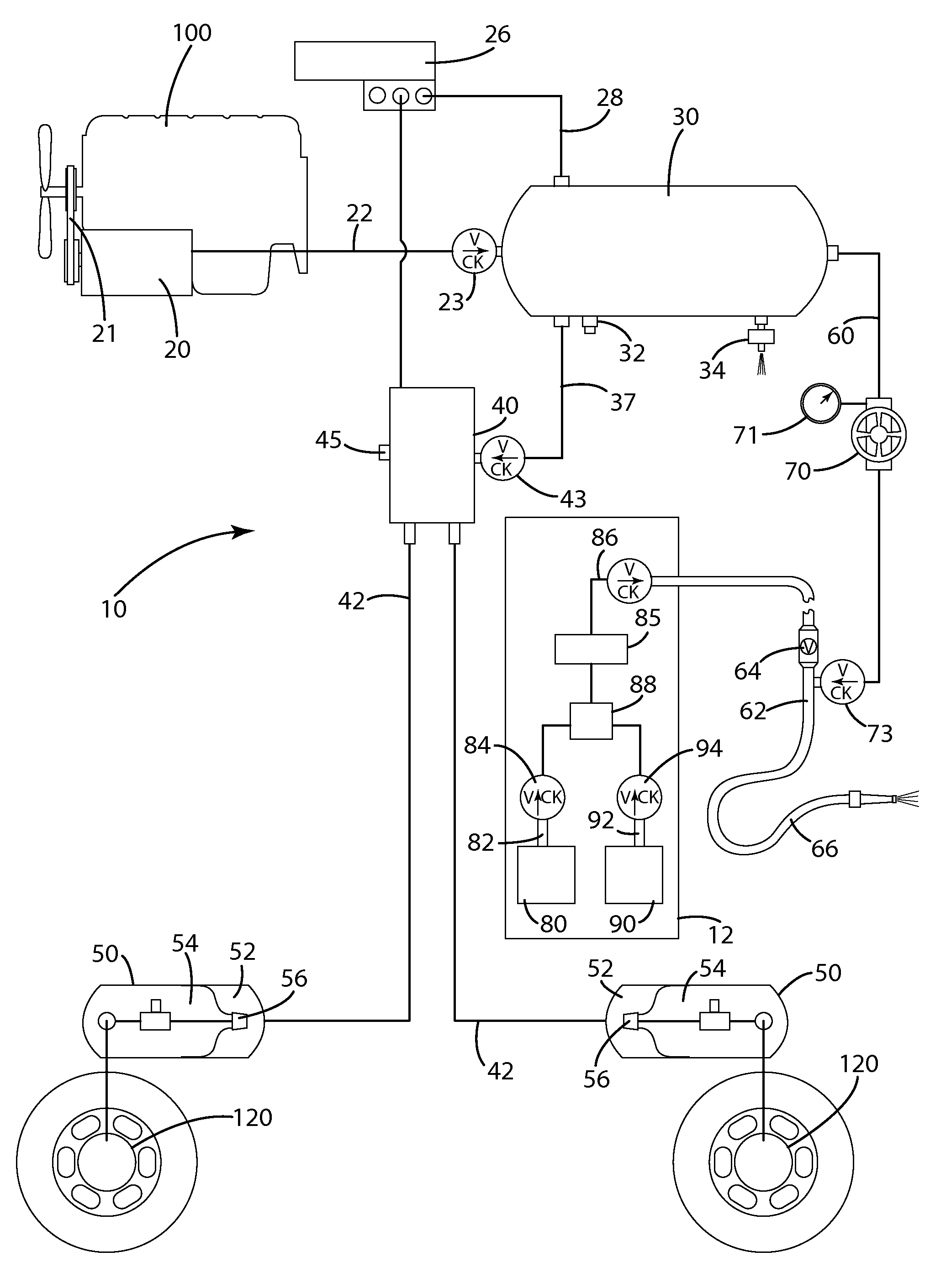
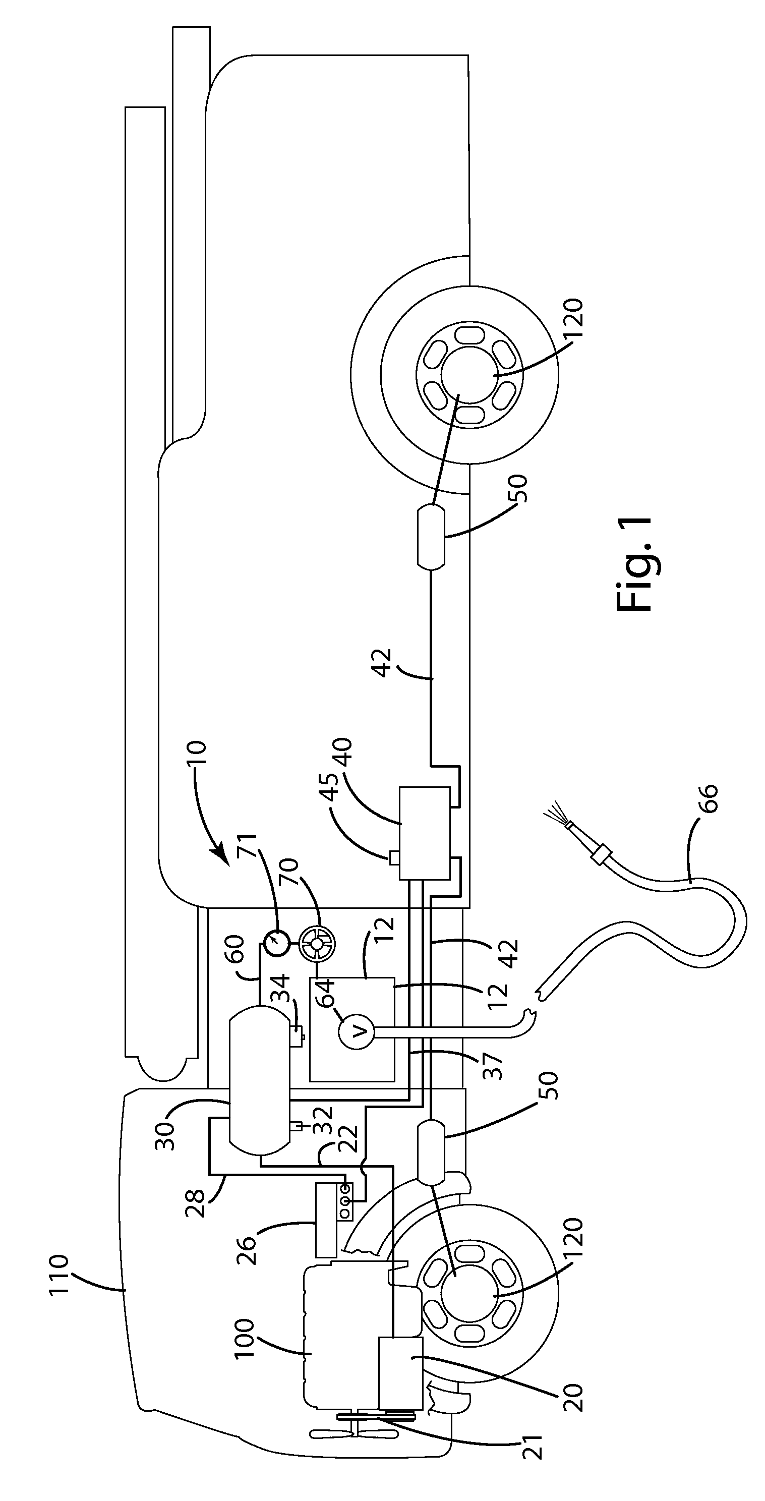
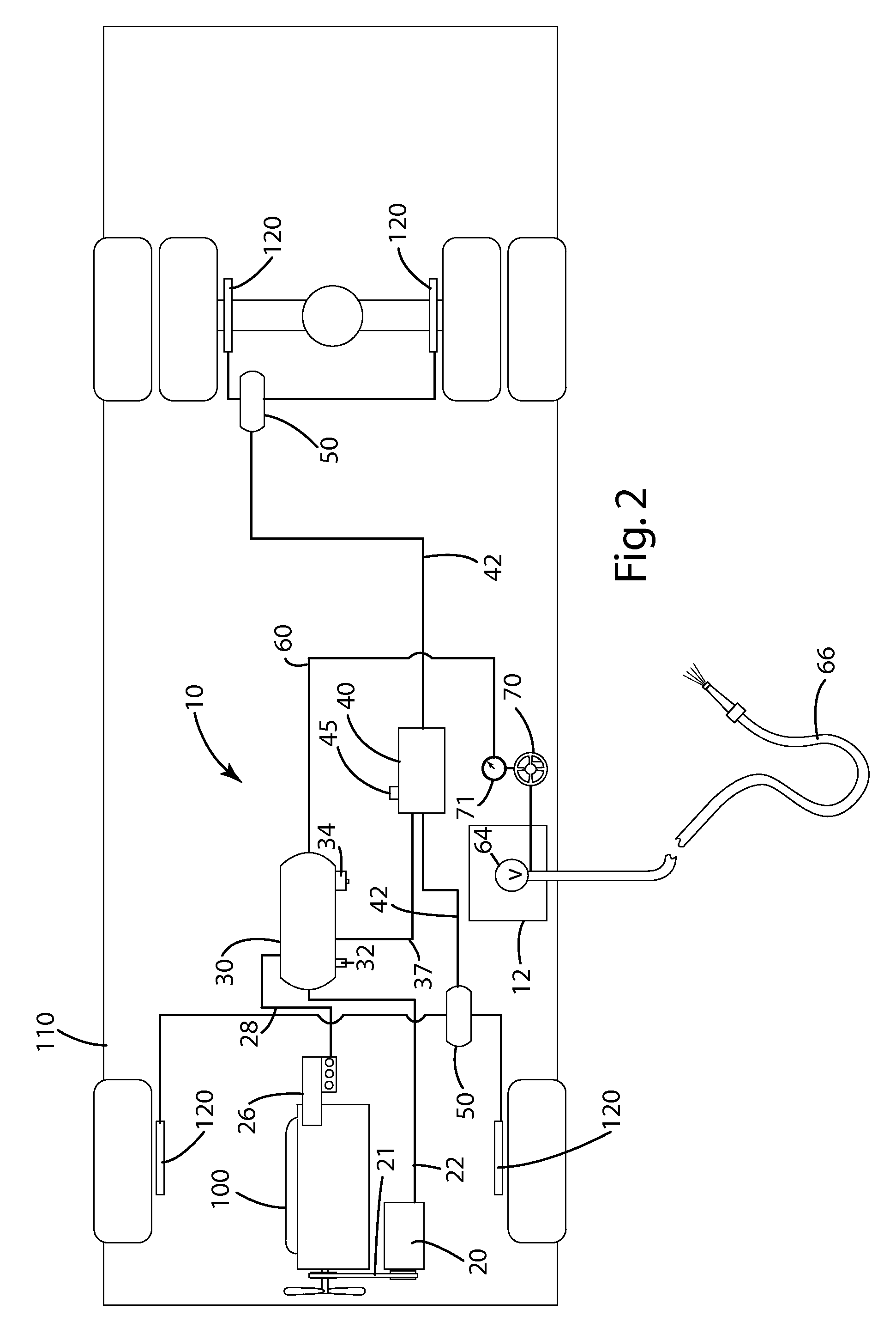
[0016]A system constructed in accordance with a current embodiment of the invention as illustrated in FIGS. 1-3 and generally designated 10. The system 10 generally includes a compressor 20 powered directly by the engine 100 of the firefighting vehicle 110. The compressor is in fluid communication with a storage tank 30, which is further in fluid communication with a dryer 40, which is in fluid communication with one or more brake system tanks 50 that supply compressed fluid to one or more brakes 120 on the truck 110. The tank 30 is also in fluid communication with a conduit 60 metered by a valve 70 to provide compressed air to combine with a liquid and foam provided by a water and foam supply system 12. For purposes of this disclosure, the system 10 is described in connection with its use with a fire truck; however, the system is well suited for use with any firefighting vehicle or device that includes a compressed air foam system and a brake system. In addi...


PUM


Abstract

A system for a firefighting vehicle including a single compressor, driven by the engine of the firefighting vehicle, which generates a compressed fluid supply for operation of both the compressed air foam system and air brakes of the firefighting vehicle. The system can include a fluid storage tank that receives compressed fluid generated by the compressor. The storage tank can be in fluid communication with a dryer and a foaming system. The dryer dries a portion of the compressed fluid and supplies the dry fluid to one or more brake system tanks, which further provide a fluid supply to one or more air brakes of the vehicle to provide a braking force to stop the vehicle. An optionally undried portion of the fluid in the fluid storage tank can be in communication with a conduit which is further in communication with a foam supply and a liquid supply which mix with the compressed fluid to create a compressed fluid foam firefighting material.

Description

BACKGROUND OF THE INVENTION[0001]The present invention relates to a compressed air foam system and methods of generating foam with such a system.[0002]Compressed Air Foam Systems (CAFSs) are used in the firefighting industry to combine compressed air with water and foam to create a homogenized mixture of foam bubbles that are dense and tightly packed, and which quickly extinguish certain types of fires. CAFSs include two system components, one of which provides foam and water, and the other of which provides compressed air at about 50-100 cubic feet per minute (CFM) to improve the foaming characteristics of the water and foam.[0003]A common CAFS is a self-contained, diesel-powered unit that is designed to fit in the bed of a pickup truck. This system includes a diesel engine, separate from the engine that powers the pickup, that operates a compressor to generate compressed air, as well as a pump that pumps water and foam to a line where it is combined with the compressed air. Althou...

Claims


Application Information

Patent Timeline
Patent Type & Authority Patents(United States)
IPC IPC(8): A62C35/02A62C2/00B05B1/24A62C29/00A62C3/07A62C3/08A62C35/00
CPCA62C5/02A62C27/00
Inventor LENZ, JR., KENNETH C.
Owner HME
Why Eureka
Try Eureka