Manhole with locking device

a technology of locking device and manhole, which is applied in the direction of door/window fittings, wing accessories, artificial islands, etc., can solve the problems of manhole cover b>4, inability to use the fastening means or manhole, and deviation of the vehicle road, so as to prevent the separation of the manhole cover, maintain the watertightness, and easily open and close the manhole cover

Inactive Publication Date: 2010-06-29
SAEGYE CAST IRON
View PDF12 Cites 9 Cited by
  • Summary
  • Abstract
  • Description
  • Claims
  • Application Information

AI Technical Summary

Benefits of technology

[0008]As described above, according to the manhole with a locking device, it is possible to prevent separation of the manhole cover from the manhole frame as well as frictional noise generated between the manhole cover and the manhole frame, and to allow an operator to readily open and close the manhole cover. In case where the manhole with a locking device is mounted in the waterside of a river, it has an effect capable of maintaining its watertightness.

Problems solved by technology

Meanwhile, in case of the manhole 1 described above, since the manhole cover 4 is merely rested on the manhole frame 2, there occurs a problem in that the manhole cover 4 is separated from the manhole frame 2 without any previous warning.
For example, as shown in FIG. 1, in case of the manhole 1 installed on a vehicle road, the manhole cover 4 is separated from the manhole frame 2 by a vehicle running at a high speed, and hence, there occur problems such as deviation of the vehicle from the vehicle road or an accident of collision with the following vehicles.
However, the fastening means or manholes are so far impossible to be put to practical use due to their structure unsuitable for casting process in spite of most manholes made of cast-ironed material, or due to in-convenience in use and troublesome problems in that the manhole cover is, once locked, hardly opened and the like as well as the complicated configuration.

Method used


Image

  • Manhole with locking device
  • Manhole with locking device
  • Manhole with locking device

Examples


Embodiment Construction

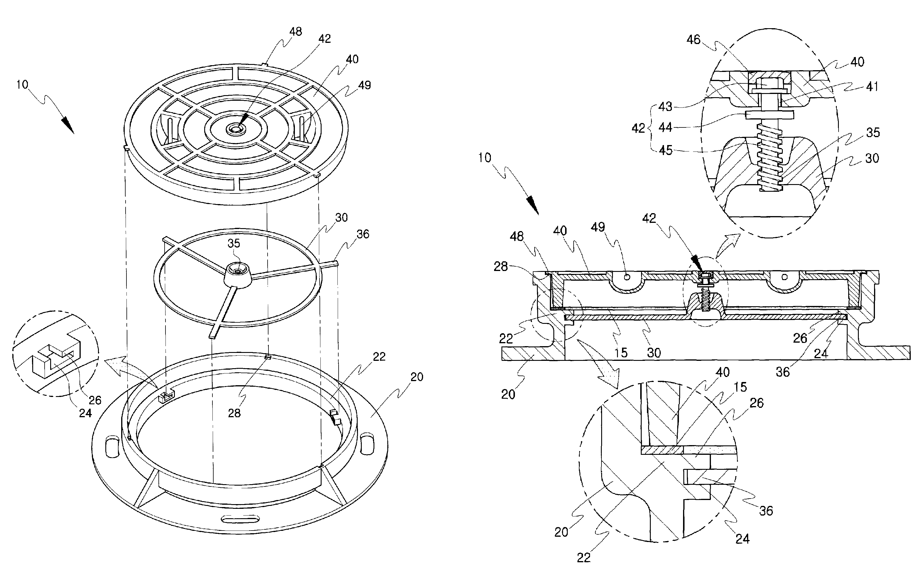
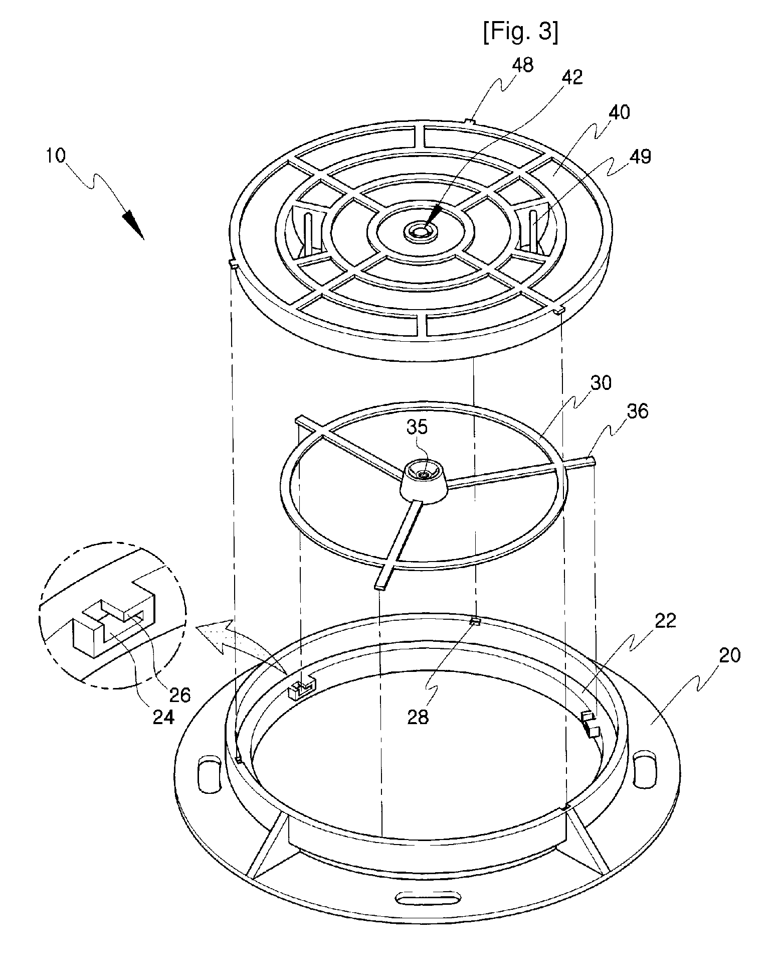
[0015]A configuration of a manhole with a locking device (hereinafter, refers to as “manhole” according to an embodiment of the present invention will be hereafter described in detail with reference to FIGS. 3 through 4.

[0016]According to the configuration of a manhole 10 according to the present invention, a manhole frame 20 has an annular retaining step 22 inwardly protruded from an inner circumferential surface thereof and has a fixing means protruded inwardly from the inner circumference of the annular retaining step 22, so that a bearing member 30 is detachably fastened to the manhole frame 20 through the fixing means. The fixing means includes a plurality of insertion slots 24 each having a latching protrusion 26, which is formed in such a manner that a part of a top surface of the insertion slot 24 is opened.

[0017]Further, the bearing member 30 has a female screw portion 35, preferably, formed on the center thereof and a plurality of fastening pieces 36 radially formed outwar...


PUM


Abstract

The present invention relates to a manhole (10) with a locking device, and more particular to a manhole with a locking device, which comprises a manhole frame (20) having a plurality of insertion slots (24) inwardly protruded from an inner circumferential surface thereof, each insertion slot (24) having a latching protrusion (26) formed in such a manner that a top surface of the insertion slots (24) is partially opened; a bearing member (30) having a female screw portion formed on the center thereof and a plurality of fastening pieces (36) radially formed outwardly from the outer circumferential edge thereof, so that the bearing member (30) is detachably fastened to the manhole frame (20); and a manhole cover (40) having a through-hole (41) centrally formed therein so that an upper portion of the vertical screw rod (42) is rotatably inserted into the through-hole (41), the vertical screw rod (42) having a male screw portion (45) formed on the lower portion thereof so as to be threadably fastened to the female screw portion (35) of the bearing member, a head portion (43) formed on the upper portion thereof so as to abut against an upside surface of the manhole cover (40), and a support portion (44) formed on the upper portion thereof so as to abut against an underside of the manhole cover (40), so that the manhole cover (40) is closed by rotating the head portion (40) of the vertical screw rod (42). Thus, in a case of the manhole (10) mounted on a vehicle road, the manhole cover (40) is prevented from being separated from the manhole frame (20) without permission by a vehicle running at a high speed as well as from frictional noise generated between the manhole cover (40) and the manhole frame (20). Further, in a case of the manhole (10) mounted on the waterside of a river, the manhole (10) maintains its watertightness and is readily opened and closed by an operator.

Description

TECHNICAL FIELD[0001]The present invention relates to a manhole with a locking device, and more particular to a manhole with a locking device, which comprises a bearing member having a female screw portion centrally formed therein and adapted to be detachably fastened to a fixing means formed on an inner circumferential surface of a manhole frame; a manhole cover having a through-hole centrally formed therein so that a vertical screw rod is rotatably inserted into the through-hole, the vertical screw rod having a male screw portion formed on a lower portion thereof so as to be threadably fastened to the female screw portion of the bearing member, and a head and a support portions formed on an upper portion thereof so as to support an upside surface and an underside surface of the manhole cover, respectively; and a means for preventing rotation of the manhole cover formed on the manhole cover, whereby the manhole cover is opened or closed from the manhole frame by fastening or loosen...

Claims


Application Information

Patent Timeline
Patent Type & Authority Patents(United States)
IPC IPC(8): E02D29/14
CPCE02D29/1427E02D29/14E05B65/006E05Y2900/612E02D2450/00
Inventor CHOI, IG-GU
Owner SAEGYE CAST IRON
Why Eureka
Try Eureka