Electronic endoscope apparatus

a technology of electronic endoscope and endoscope body, which is applied in the field of electronic endoscope body configuration, can solve the problems of insufficient utilization of ccd resolution power and expensive apparatus, and achieve the effects of simplifying the transmission structure of control signals, low cost and low cos

Inactive Publication Date: 2010-08-10
FUJI PHOTO OPTICAL CO LTD
View PDF20 Cites 53 Cited by
  • Summary
  • Abstract
  • Description
  • Claims
  • Application Information

AI Technical Summary

Benefits of technology

[0012]The present invention was developed in view of the above situations. It is therefore an object of the invention to provide an electronic endoscope apparatus capable of acquiring high-definition television pictures with a simple structure and at low costs without lowering the resolution power even in a case of connecting an electronic endoscope having solid-state pickup elements of different pixel numbers incorporated therein by utilizing digitally-processed picture output to supply the same to a personal computer, etc. In addition, it is another object of the invention to provide an electronic endoscope apparatus capable of simplifying a transmission structure of control signals to a recording unit in a case of video-recording and storing high-definition television pictures.
[0020]Also, although there is a differential circuit in which a pulse transformer and a capacitor are employed as an input / output (transmission) circuit of the differential signals, if the proof pressure of the pulse transformer and capacitor is set to, for example, 4 kV or more, which is required for an electronic endoscope, in the invention according to the third aspect, it is possible to easily and electrically separate the high-definition television system converter side (power source) from the electronic endoscope (differential signal outputting portion) side.

Problems solved by technology

However, as described above, in the case of converting NTSC signals to high-definition television signals, the high-definition television signals are restricted by the resolution power of the NTSC picture signals, wherein there is a problem in that the CCD resolution power upgraded in quality cannot be sufficiently utilized.
In addition, since CCDs having different pixel numbers are incorporated, as described above, in an electronic endoscope, it is useless or wasteful in terms of costs that converting circuits to high-definition television signals are disposed, or renewed (or replaced) in a processor unit in response to differences in the CCD pixel number and change in upgrading the pixel number, and the apparatus becomes expensive.
Further, as regards equipment used in medical fields, strict standards are requested in regard to EMC (Electro-Magnetic Compatibility) and electrical safety, and it is unrealistic that the above-described medical standards are satisfied in large equipment such as a personal computer in order to convert signals to high-definition television signals.

Method used


Image

  • Electronic endoscope apparatus
  • Electronic endoscope apparatus
  • Electronic endoscope apparatus

Examples


first embodiment

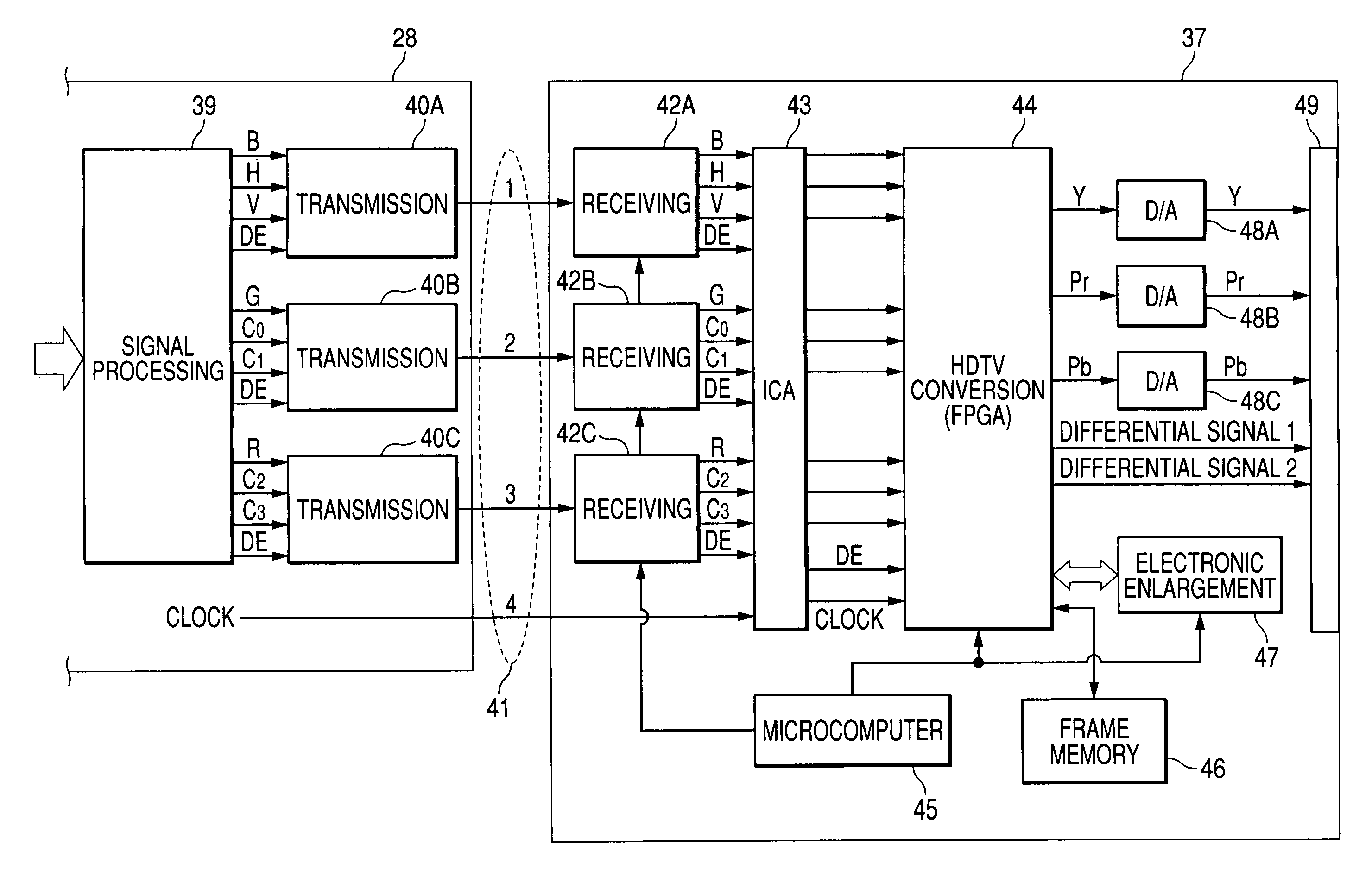
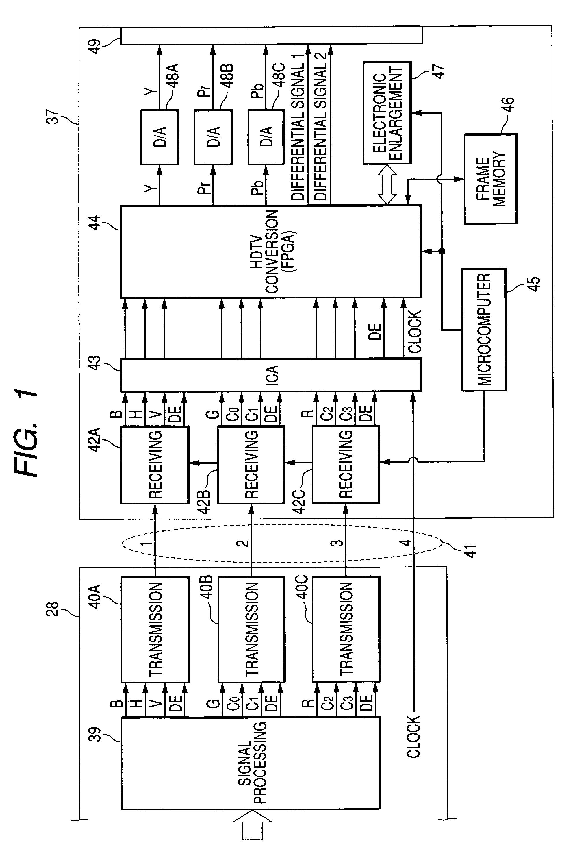
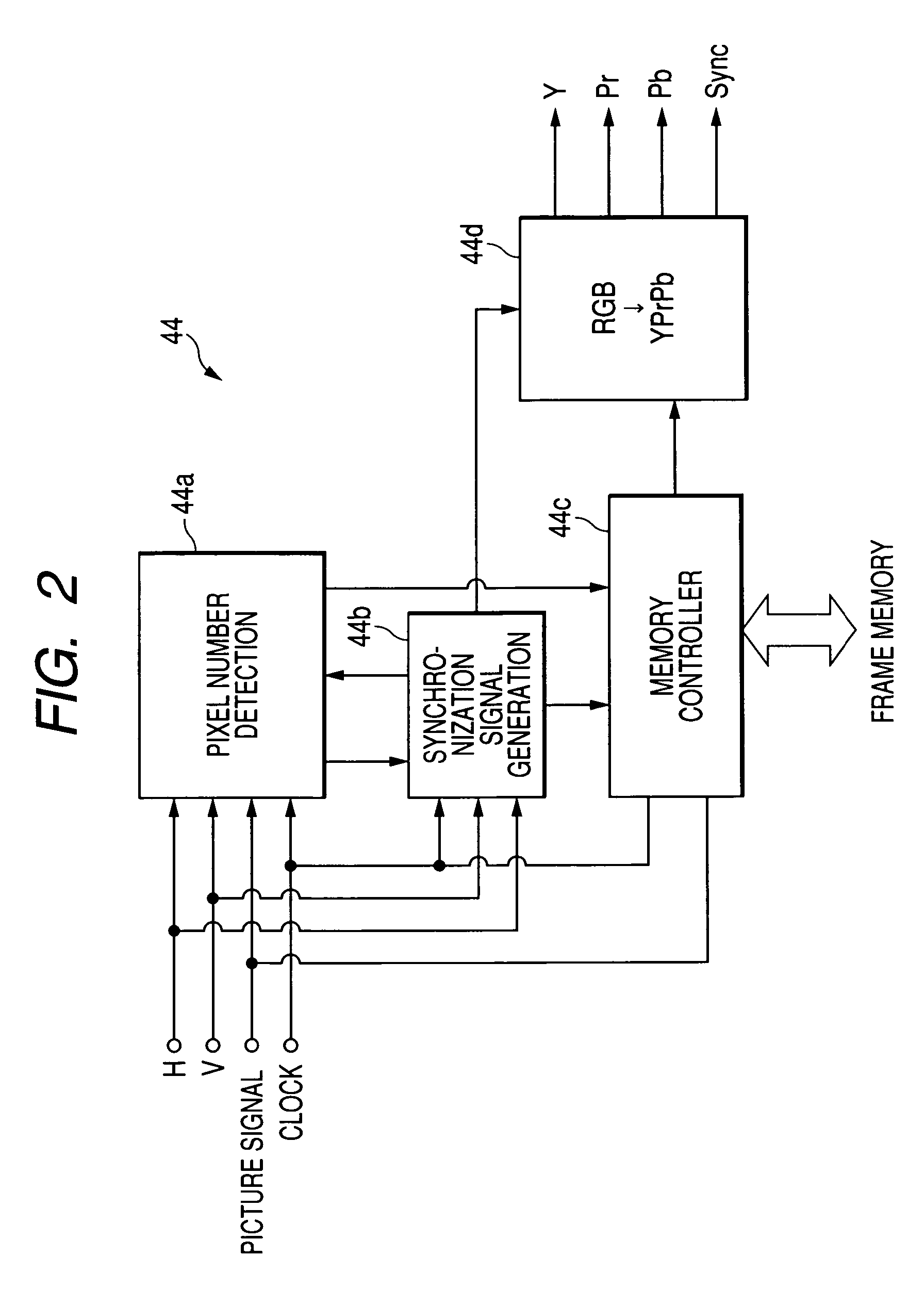
[0036]FIG. 1 through FIG. 3 show a configuration of an electronic endoscope apparatus according to a first embodiment. A description is given of a general configuration thereof with reference to FIG. 3. In FIG. 3, a CCD 11 which is a solid-state pickup element is provided at a distal end of an electronic endoscope (Electroscope) 10. Various types of CCDs, for example, 400000-pixel type, 800000-pixel type, and 1300000-pixel type are incorporated as the CCD 11. Also, a correlation doubling sampling (CDS) circuit 12 for sampling picked up signals outputted from the CCD 11 and a memory (EEPROM) 13 for storing identification information and picture processing information of the electronic endoscope 10 are provided therein. Also, light of a light source device (not illustrated) is supplied to the electronic endoscope 10 via a light guide, and by outputting illumination light through the distal end, an object to be observed is picked up by the CCD 11. And, various types of electronic endos...

second embodiment

[0041]FIG. 2, FIG. 10 and FIG. 11 show configurations of an electronic endoscope apparatus according to the second embodiment. In the second embodiment, parts identical with those previously described with reference to the foregoing figures are denoted by the same or corresponding reference numerals in the corresponding figure and will not be discussed again.

[0042]In the second embodiment, as shown in FIG. 11 indicating a general configuration thereof, a video recording / storing switch 14 is provided at the operation portion (or the operation portion of a processor unit 16) of the electronic endoscope 10, and it is possible to record endoscopic (analog or digital) pictures in a recording unit (HDTV recorder) and a filing apparatus, which is an external device) by using the video recording / storing switch 14.

[0043]Record controlling signals outputted from the above-described video recording / storing switch 14 are supplied from the microcomputer 24 to the DVI circuit 28 as in the signal ...


PUM


Abstract

An electronic endoscope apparatus comprises: a processor unit; and an electronic endoscope having a solid-state pickup element, the electronic endoscopes being capable of connecting to the processor unit, so as to generate digital picture signals, wherein the processor unit comprises a differential signal outputting portion that generates digital picture signals corresponding to a pixel number of the solid-state pickup element and corresponding to a display standard for an external computer, parallel-serially converts the digital picture signals, and outputs the converted signals as differential signals, and wherein the electronic endoscope apparatus further comprises a high-definition television system converter that detects the pixel number of the digital picture signals based on the differential signals, converts the digital picture signals to high-definition television signals based on the detected number of pixels and outputs the high-definition television signals, the high-definition television system converter being detachably connected to the differential signal outputting portion.

Description

RELATED APPLICATIONS[0001]This application claims the priority of Japanese Patent Application Nos. filed on Apr. 16, 2004 and Apr. 19, 2004, respectively, which are incorporated herein by reference.BACKGROUND OF THE INVENTION[0002]1. Field of the Invention[0003]The present invention relates to a configuration of an electronic endoscope apparatus capable of outputting pictures of an object to be picked up, into a high-definition television system monitor particularly in an environment where various types of electronic endoscopes having different numbers of pixels of a solid-state pickup element can be used.[0004]2. Description of the Related Art[0005]An electronic endoscope apparatus has a CCD (Charge Coupled Device), etc., which is a solid-state pickup element, incorporated at a distal end of an electronic endoscope (electroscope), and the CCD picks up an object to be picked up, on the basis of illumination brought about by a light source unit. And, picked-up signals obtained by the...

Claims


Application Information

Patent Timeline
Patent Type & Authority Patents(United States)
IPC IPC(8): H04N7/18A61B1/04A62B1/04G09G5/00H04N5/225H04N5/77
CPCG09G5/006H04N5/335G09G5/005G09G2340/0407G09G2340/0485H04N5/77H04N7/0125H04N2005/2255H04N23/555H04N25/00
Inventor ABE, KAZUNORI
Owner FUJI PHOTO OPTICAL CO LTD
Why Eureka
Try Eureka