

Adjustable wheeled IV stand
a technology of iv stand and wheel, which is applied in the direction of washing stand, machine support, other domestic objects, etc., can solve the problems that the apparatus, however, requires a substantial amount of space, and achieve the effect of increasing stability
- Summary
- Abstract
- Description
- Claims
- Application Information
AI Technical Summary
Benefits of technology
Problems solved by technology
Method used
Image

Examples
Embodiment Construction
[0019]The following description will be made with reference to the drawings where when referring to the various figures, it should be understood that like numerals or characters indicate like elements. Further, before the present invention is described, it is to be understood that this invention is not intended to be limited to particular embodiments or examples described, as such may, of course, vary.
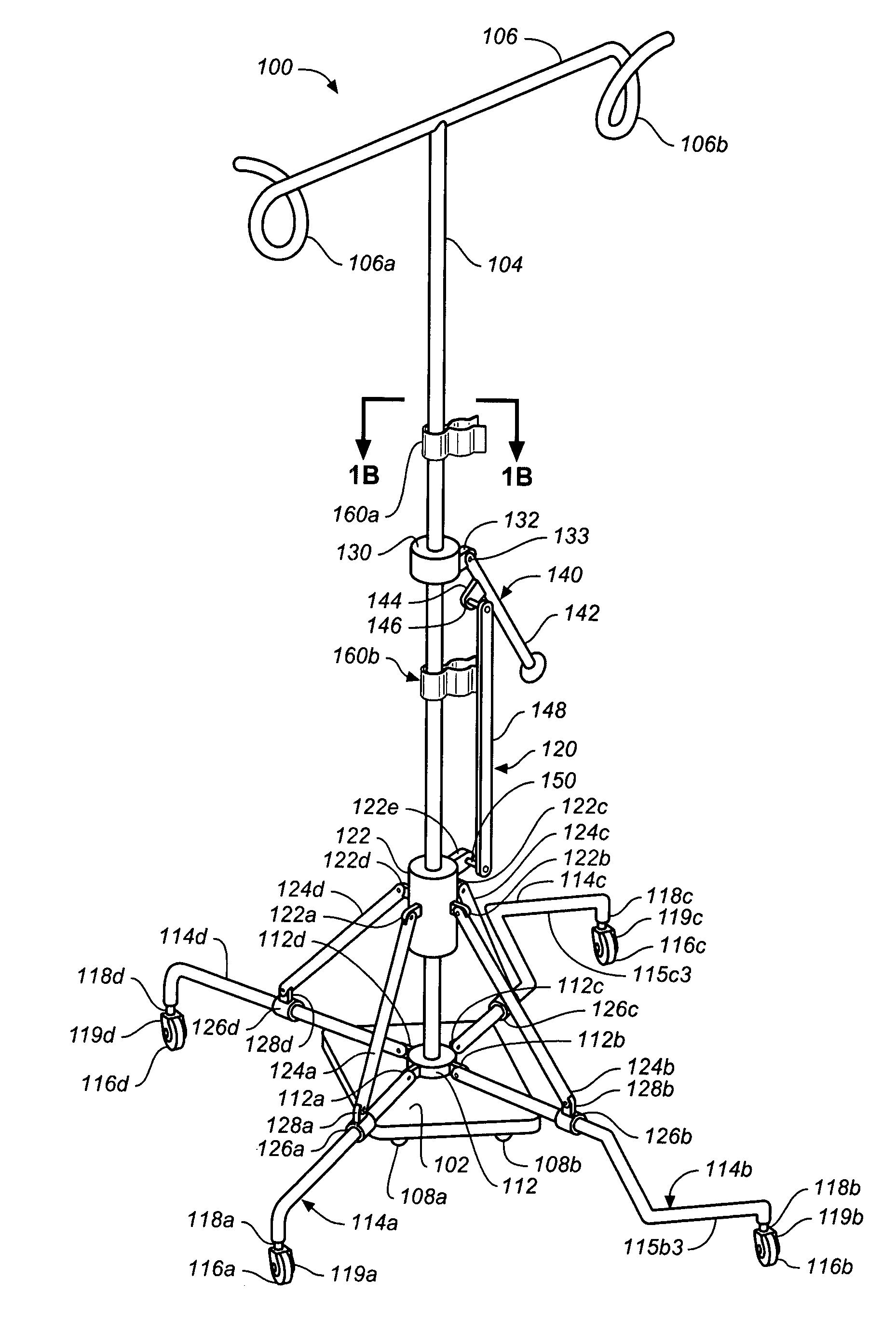
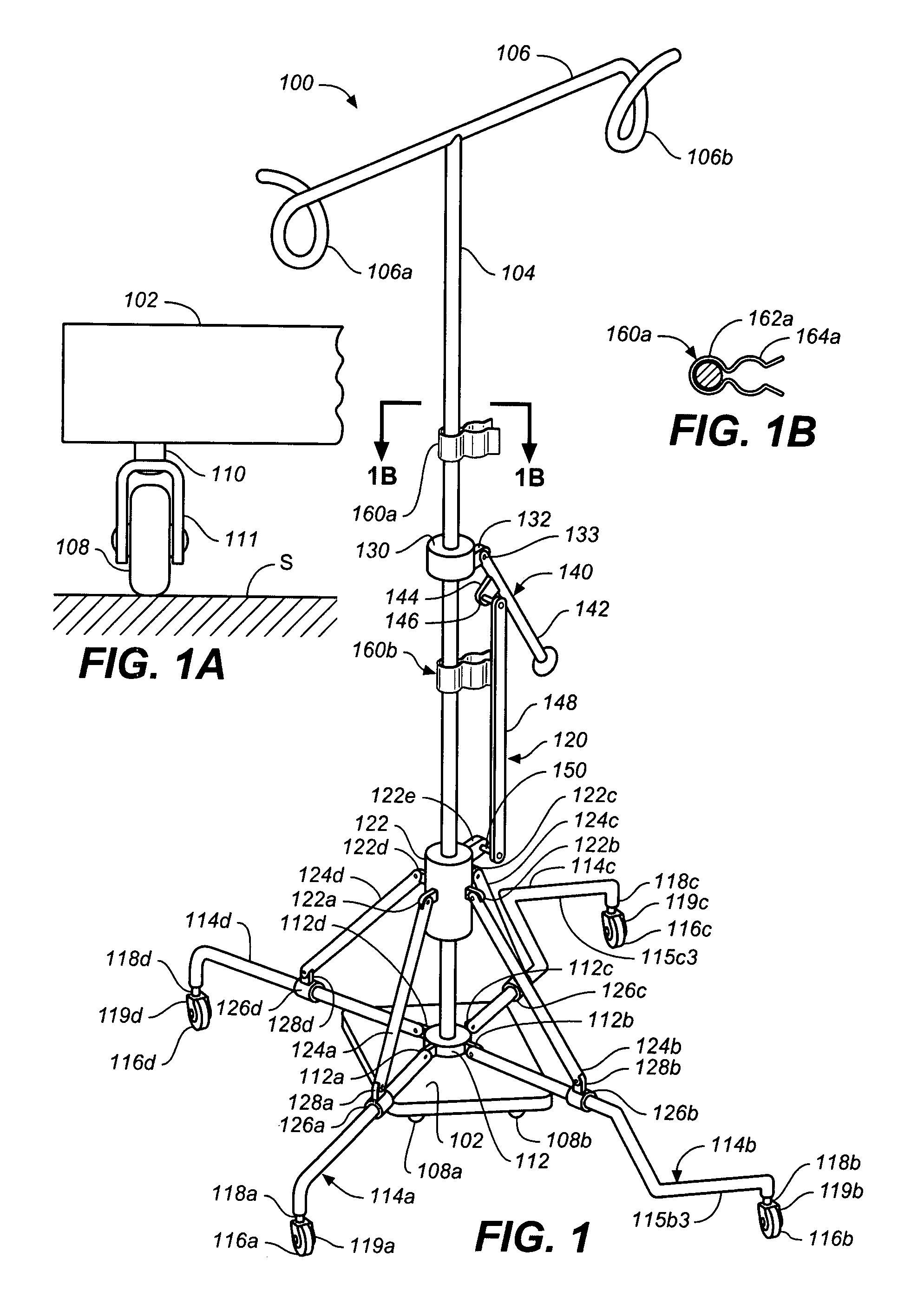
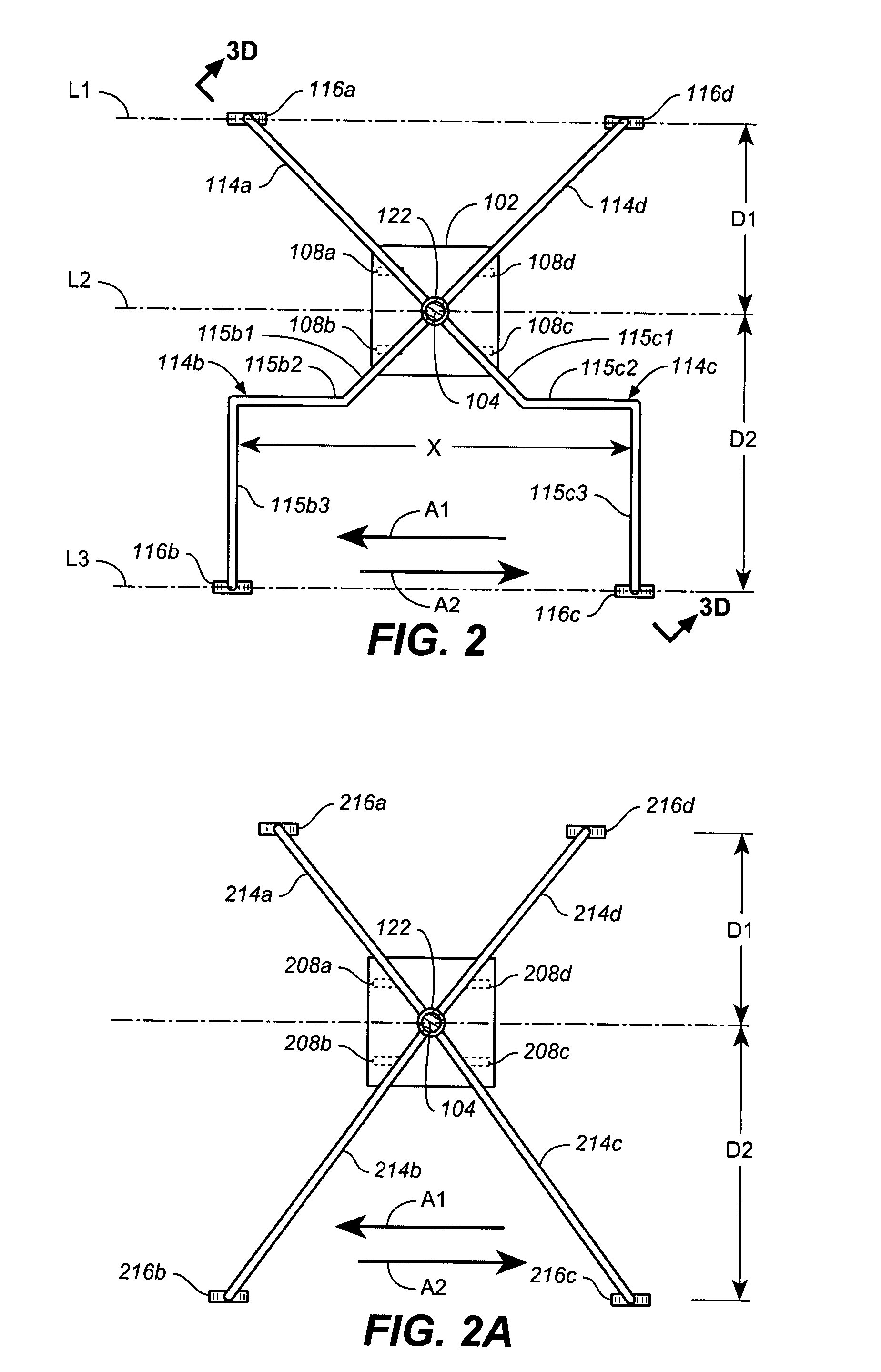
[0020]Referring to FIG. 1, one embodiment of a portable IV stand is shown and generally designated with reference numeral 100. IV stand 100 generally has a wheelbase that can be adjusted between first and second configurations to accommodate different modes of use. The wheelbase can be measured between any two wheels when in a first configuration and any two wheels when in a second configuration. For example, the wheelbase in FIG. 3A can be measured as the distance between the centers of wheels 108a and 108b and the wheelbase in FIG. 3D can be measured as the distance between centers o...
PUM
 Abstract
Description
Claims
Application Information