Suction valve

a suction valve and suction end technology, applied in the field of direct response valves, can solve the problems of the suction end configured to receive my new suction valve failing, and achieve the effect of substantial cost savings and minimizing the likelihood of proppant being knocked out of suspension

Inactive Publication Date: 2011-02-22
FORUM US
View PDF21 Cites 26 Cited by
  • Summary
  • Abstract
  • Description
  • Claims
  • Application Information

AI Technical Summary

Benefits of technology

[0004]In light of the problems associated with the suction valves commonly used within high-pressure pumps, it is a principal object of the invention to provide a suction valve that minimizes the likelihood of proppant being knocked out of suspension. My suction valve, thus, offers few impediments to flow of fluids through it. As a result, fracture fluids with higher than normal concentrations of suspended proppants can be pumped with substantial cost savings accruing to the user.
[0006]It is a further object of the invention to provide a suction valve of the type described that is easily and quickly installed and serviced through a suction passage in a fluid end.
[0007]It is an object of the invention to provide improved features, and arrangements thereof, in a suction valve for the purposes described that is lightweight in construction, inexpensive to manufacture, and dependable in use.

Problems solved by technology

It is unlikely, then, that a fluid end configured to receive my new suction valve will fail from the development of excessive, internal stresses and cracks.

Method used


Image

  • Suction valve
  • Suction valve
  • Suction valve

Examples


Embodiment Construction

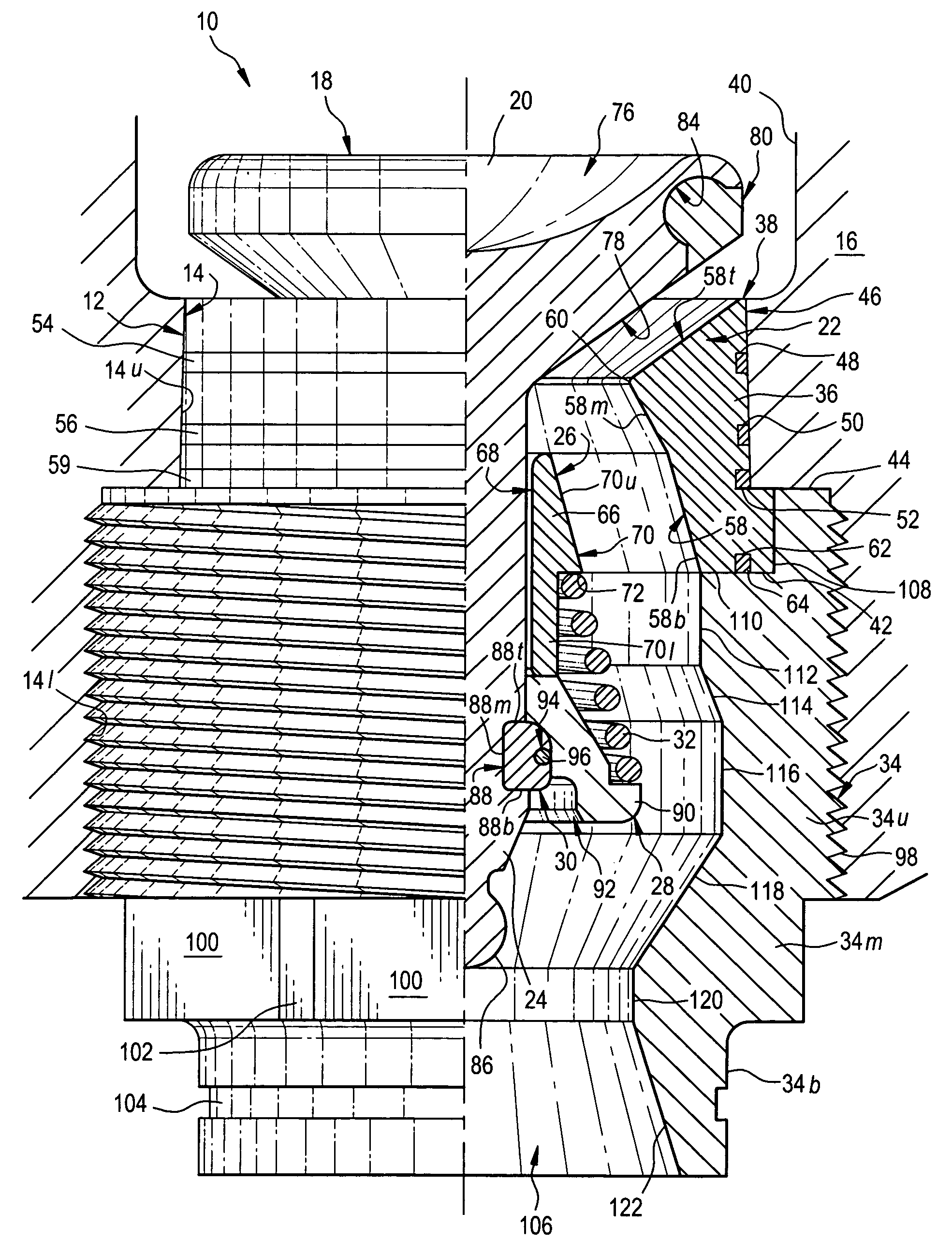
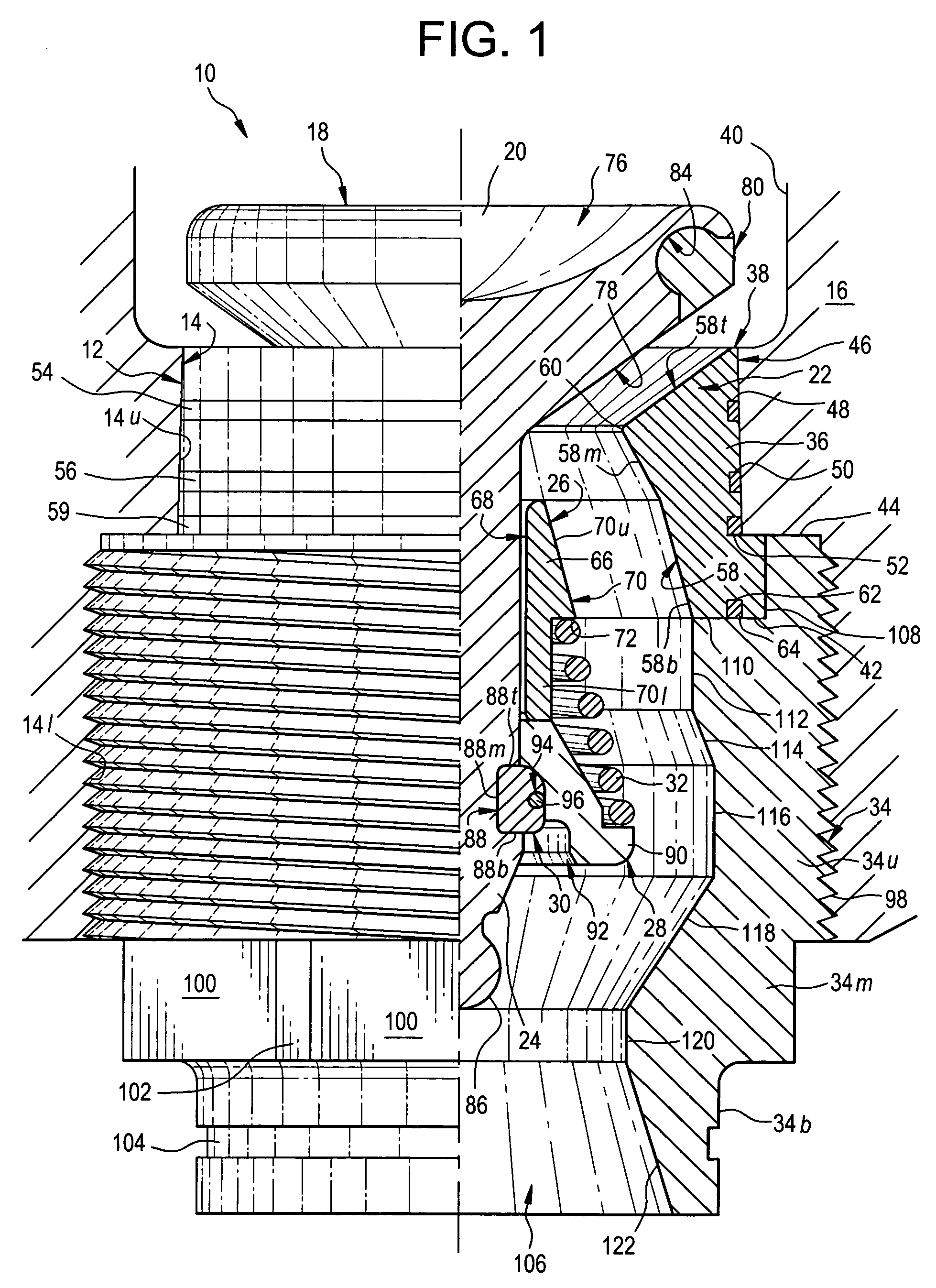
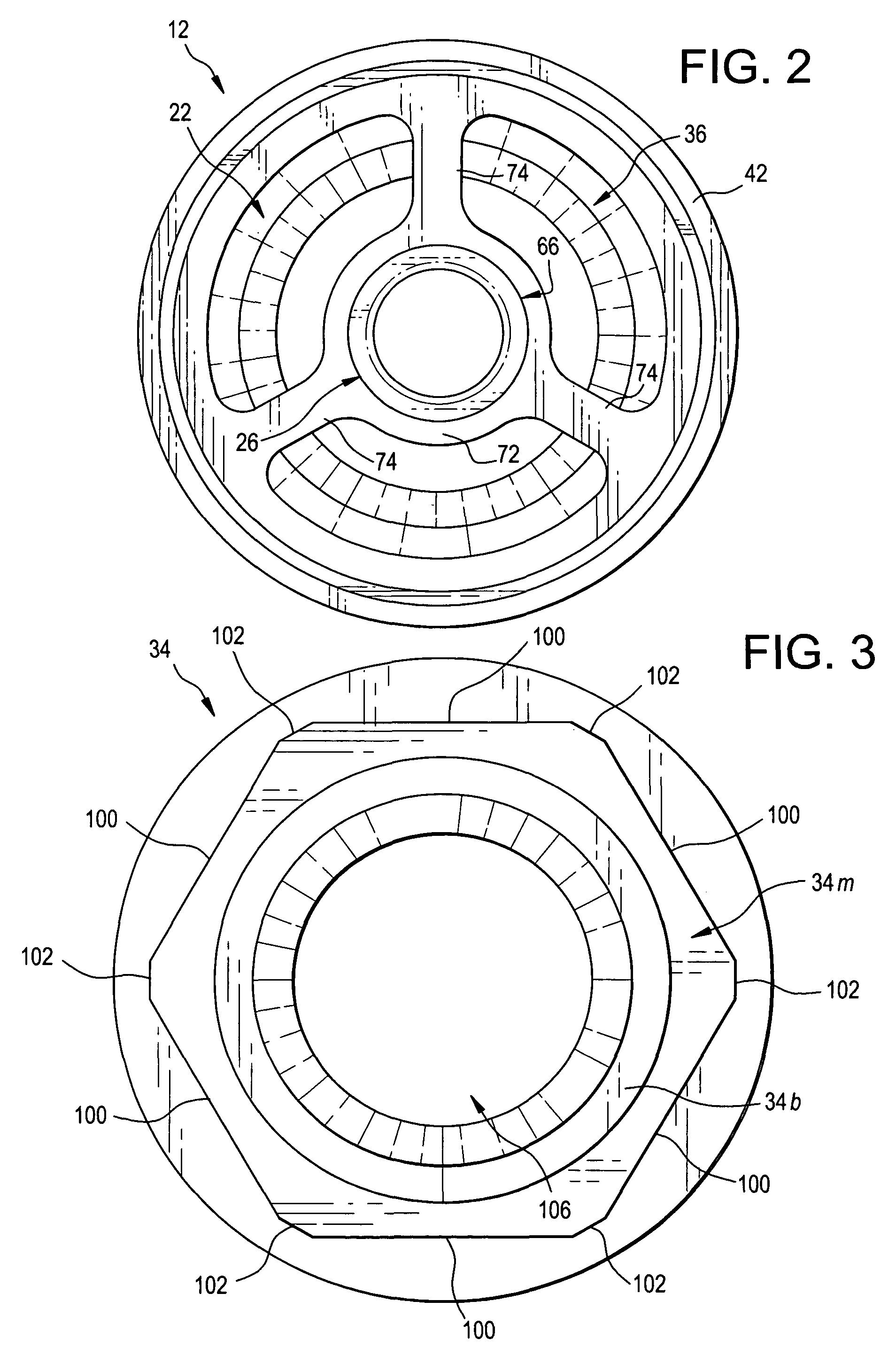
[0015]Referring now to the FIGS., a suction valve in accordance with the present invention is shown at 10. Valve 10 includes a valve seat and guide assembly 12 for positioning in a suction passage 14 of a fluid end 16 and a piston 18 that moves within assembly 12 to control the flow of fluid through passage 14. Piston 18 has a head 20 for engaging the seat portion 22 of assembly 12 and a stem 24 extending downwardly from head 20 through the guide portion 26 of assembly 12. A valve keeper 28 is fitted upon the bottom of stem 24 and is retained there by a split ring 30. A compressed spring 32 is positioned between guide portion 26 and keeper 28 for normally retaining head 20 in engagement with seat portion 22 to prevent fluid flow through passage 14. A valve retainer 34 is screwed into suction passage 14 to retain the balance of valve 10 within fluid end 16 and provide for the attachment of valve 10 to a suction manifold (not shown).

[0016]Seat portion 22 comprises an outer ring 36 tha...


PUM


Abstract

A suction valve seat and guide assembly has an outer ring and a peripheral flange projecting outwardly from the bottom of the outer ring, and an inner surface with a top part sloping downwardly and inwardly toward the center of the outer ring. The outer ring has an outer surface that slopes upwardly and inwardly from the flange. The guide has an inner ring positioned within the outer ring and a number of spaced-apart fins connecting the inner ring to the outer ring. A retainer has an internal passageway, an externally threaded, upper segment within the top of which is fitted the peripheral flange of the seat; a middle segment that is affixed to the bottom of the upper segment and has a polygonal cross section for easy gripping by a wrench; and, a bottom segment that is affixed to the bottom of the middle segment.

Description

FIELD OF THE INVENTION[0001]The present invention relates generally to fluid handling apparatus and, more particularly, to direct response valves of reciprocating type.BACKGROUND OF THE INVENTION[0002]Hydraulic fracturing can increase the rate of production of oil and gas from low-permeability reservoirs. As is well known, hydraulic fracturing increases the permeability of reservoir rocks by opening channels through which oil and gas can travel to recovery wells. During hydraulic fracturing, a fluid is pumped under high pressure into a subterranean reservoir where it splits the reservoir rock open. A proppant, like sand, is often added to the pumped fluid and is carried in suspension into the newly formed fractures. When pumping ceases, the fractures partially close on the proppant, leaving open channels for oil and gas to flow to recovery wells.[0003]High-pressure pumps make possible hydraulic fracturing procedures or “frac jobs.” These pumps have “fluid ends” within which a number...

Claims


Application Information

Patent Timeline
Patent Type & Authority Patents(United States)
IPC IPC(8): F16K15/06
CPCF16K15/063F16K15/18Y10T137/7868Y10T137/7932Y10T137/7559Y10T137/7931
Inventor VICARS, BERTON L.
Owner FORUM US
Why Eureka
Try Eureka