Light-directing apparatus with protected reflector-shield and lighting fixture utilizing same

a technology of reflector shield and light-directing apparatus, which is applied in the field of light-directing apparatus with protected reflector shield and lighting fixture utilizing same, can solve the problems of difficult to achieve continuous combination of advantages, and achieve the effect of facilitating illumination and facilitating illumination

Active Publication Date: 2011-02-22
IDEAL IND LIGHTING LLC
View PDF32 Cites 29 Cited by
  • Summary
  • Abstract
  • Description
  • Claims
  • Application Information

AI Technical Summary

Benefits of technology

[0007]Another object of this invention is to provide light-directing apparatus and lighting fixture which maximize the light directed toward a preferential side and minimize light directed toward the opposite (non-preferential) side.
[0008]Another object of this invention is to provide lighting fixtures for uses such as roadway and parking-lot illumination that have high-efficiency light-directing apparatus while satisfying requirements for minimizing trespass light.
[0011]Another object of this invention is to provide an LED-based light-directing apparatus having light-managing components which are protected from damage, degradation and wear over an extended period of time, even in difficult use environments.
[0020]The reflective front surface is preferably entirely within the lensing member. Such enclosure provides highly desirable protection for the reflective surface, virtually eliminating damage, degradation and wear from exposure to elements.
[0027]In some embodiments of the inventive lighting fixture, the lenses have preferential sides in the same lateral direction, thereby to facilitate illumination toward one lateral direction.
[0028]In other embodiments, the lenses have preferential sides in different lateral directions, thereby to facilitate illumination in different lateral directions. The lenses may be arranged in a substantially circular pattern, and each lens has a preferential side oriented in a substantially radially outward direction with respect to the circular pattern. Some of such other embodiments may have subsets of the emitters and the corresponding lenses, with the subsets configured for directing light in different lateral directions.

Problems solved by technology

Such continued combination of advantages can be difficult to achieve because of susceptibility of light-managing components to damage, degradation and wear over a period of time.

Method used


Image

  • Light-directing apparatus with protected reflector-shield and lighting fixture utilizing same
  • Light-directing apparatus with protected reflector-shield and lighting fixture utilizing same
  • Light-directing apparatus with protected reflector-shield and lighting fixture utilizing same

Examples


Embodiment Construction

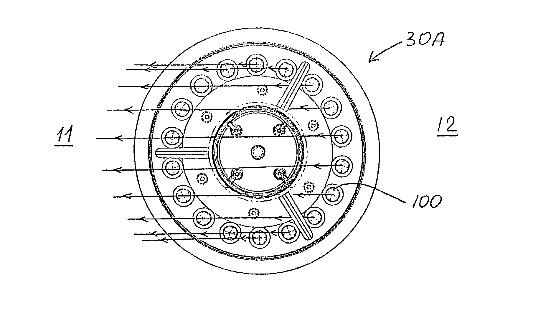
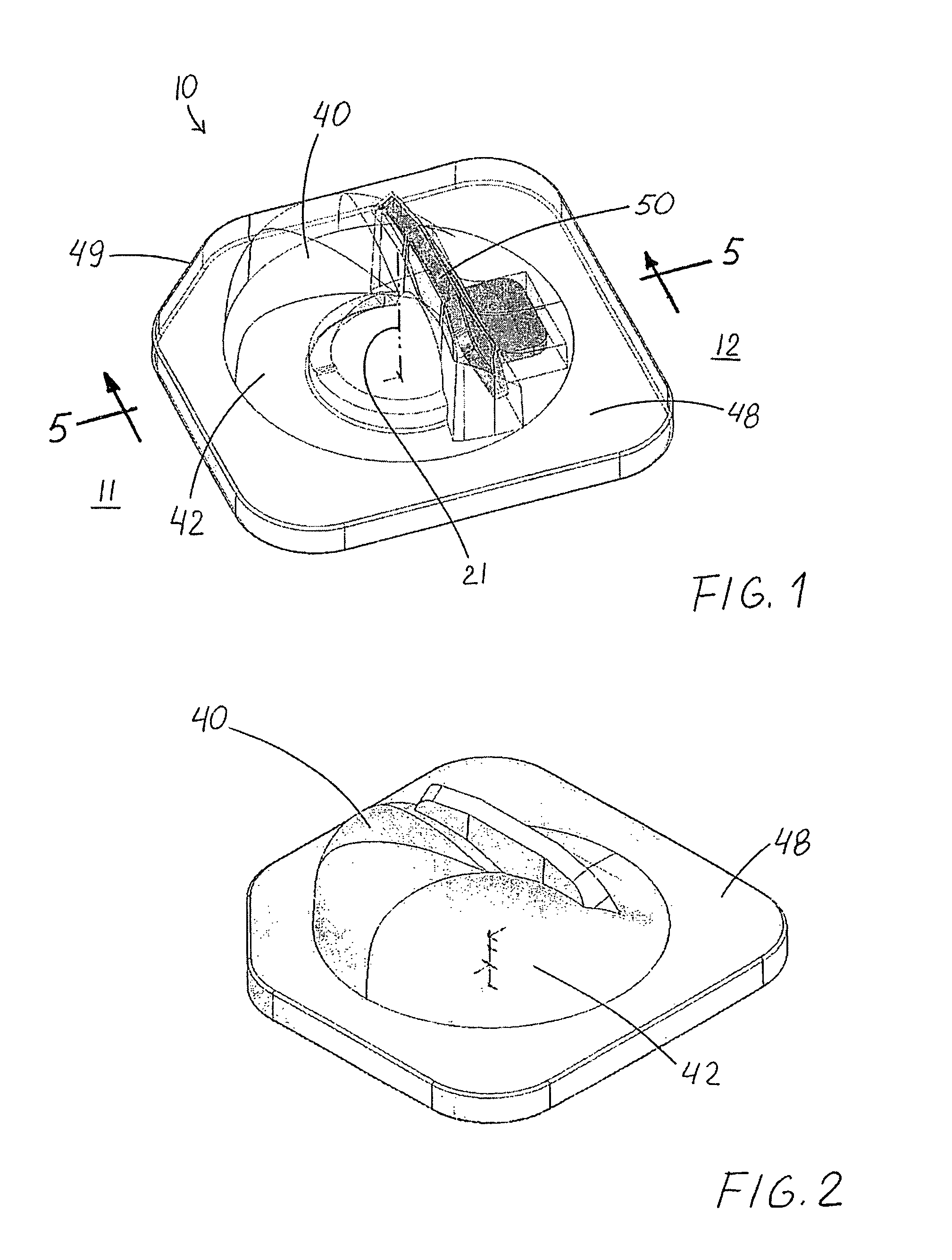
[0059]FIGS. 1-14 show preferred embodiments of an inventive light-directing apparatus 10 in accordance with this invention for off-axial preferential-side distribution of light from a light emitter 20 which has an emitter axis 21. FIGS. 15-19 illustrate preferred embodiments of another aspect of this invention which is a lighting fixture 30 utilizing light-directing apparatus 10.

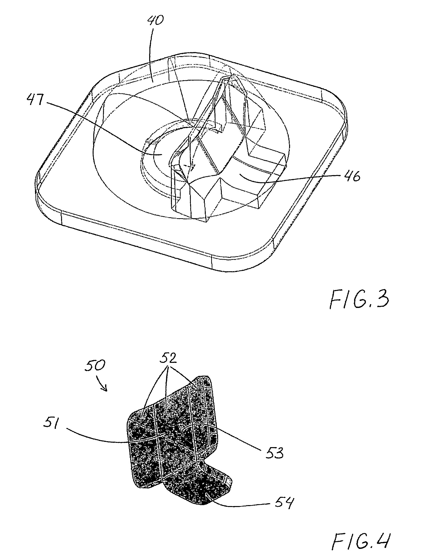
[0060]Inventive light-directing apparatus 10 includes a lensing member 40 positioned over light emitter 20 and a shield member 50. As best seen in FIGS. 3, 5 and 7-9, lensing member 40 has a proximal end 41 substantially transverse emitter axis 21 and an outer surface 42 configured for refracting light from emitter 20. In such embodiments, shield member 50 has been inserted into lensing member 40.

[0061]FIG. 6 shows a light-directing apparatus 10A which is another embodiment of the invention, in this case with shield member 50A embedded within lensing member 40A in a position in the path of light emitter towa...


PUM


Abstract

A light-directing apparatus for off-axial preferential-side distribution of light from a light emitter having an emitter axis, including a lensing member positioned over the light emitter a shield member embedded within the lensing member in a position in the path of light emitted toward a non-preferential side. The lensing member having a proximal end substantially transverse the emitter axis and an outer surface configured for refracting light from the emitter. The shield member may be snugly received in a shield-receiving void of an inner surface of the lensing member. Alternatively, the shield member is embedded by the lensing member having been molded thereabout. Another aspect of this invention is a lighting fixture utilizing such light-directing apparatus.

Description

FIELD OF THE INVENTION[0001]The invention relates generally to the field of lighting systems and, more particularly, to apparatus for utilizing LED light sources for illuminating areas with predefined patterns of light intensity.BACKGROUND OF THE INVENTION[0002]There is a continuing need for lighting apparatus which is low-cost and energy efficient. LEDs (light-emitting diodes) provide light sources which are energy efficient, and advances in LED technology are providing even greater efficiencies over time.[0003]Some of the newer applications for LED-based lighting systems are roadway and parking lot lighting in which there are desired performance and light-distribution characteristics. More specifically, it is desirable that certain regions generally beneath a light fixture be illuminated, while certain neighboring regions are essentially non-illuminated. Along roadways and in parking lots, there is a need to be able to direct light in a particular preferential lateral direction (e...

Claims


Application Information

Patent Timeline
Patent Type & Authority Patents(United States)
IPC IPC(8): F21V13/04
CPCF21V5/04F21V13/04F21V13/10F21V13/12F21V13/02F21K9/50F21V11/16F21V19/02F21K9/60F21V14/00F21W2131/103F21Y2115/10F21V17/005F21S8/085F21V9/40F21K9/68F21K9/69F21V5/008
Inventor WILCOX, KURT S.
Owner IDEAL IND LIGHTING LLC
Why Eureka
Try Eureka