Light-Directing LED Apparatus

a technology of led lighting and led lamps, applied in the field of light-directing led lamps, can solve the problems of limited efforts made to develop light-directing, falling well short of the requirements to avoid trespass lighting, etc., and achieve the effects of minimizing trespass lighting, maximizing light directed, and minimizing light directed

Active Publication Date: 2008-10-02
IDEAL IND LIGHTING LLC
View PDF99 Cites 167 Cited by
  • Summary
  • Abstract
  • Description
  • Claims
  • Application Information

AI Technical Summary

Benefits of technology

[0008]Another object of this invention is to provide LED light-directing apparatus which maximizes the light directed toward a preferential side and minimizes light directed toward the non-preferential side.
[0009]Another object of this invention is to provide LED light-directing apparatus which minimizes trespass lighting by minimizing the distance into the area on the non-preferential side that light is directed.
[0011]Another object of this invention is to provide LED light-directing apparatus which directs a maximum amount of light with only a single refraction to achieve improved control of the directed light.

Problems solved by technology

In addition, some limited efforts have been made to develop light-directing LED apparatus using small lenses over small LED light emitter packages, and utilizing lenses intended to redirect some amount of emitted light to one side preferentially.
However, such lenses, utilizing lens surfaces having one or more projecting elements and extensive regions of discontinuity, fall well short of requirements to avoid trespass lighting.

Method used


Image

  • Light-Directing LED Apparatus
  • Light-Directing LED Apparatus
  • Light-Directing LED Apparatus

Examples


Embodiment Construction

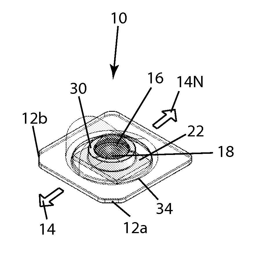
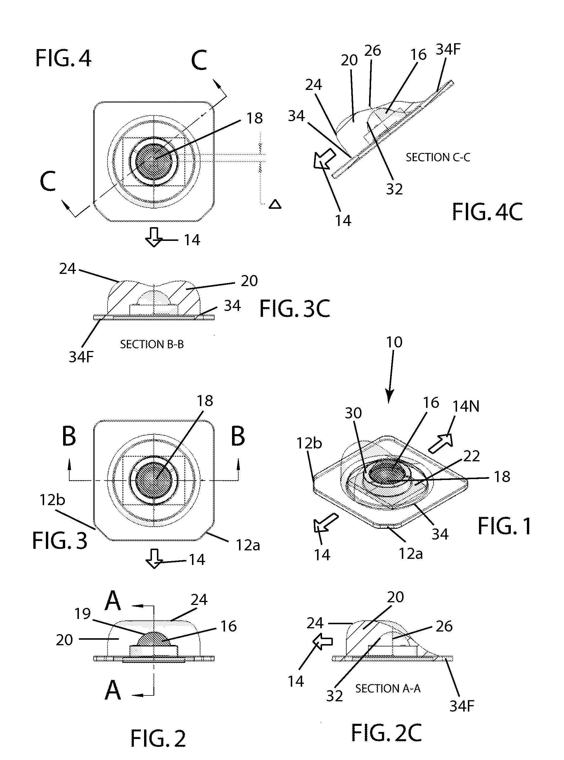
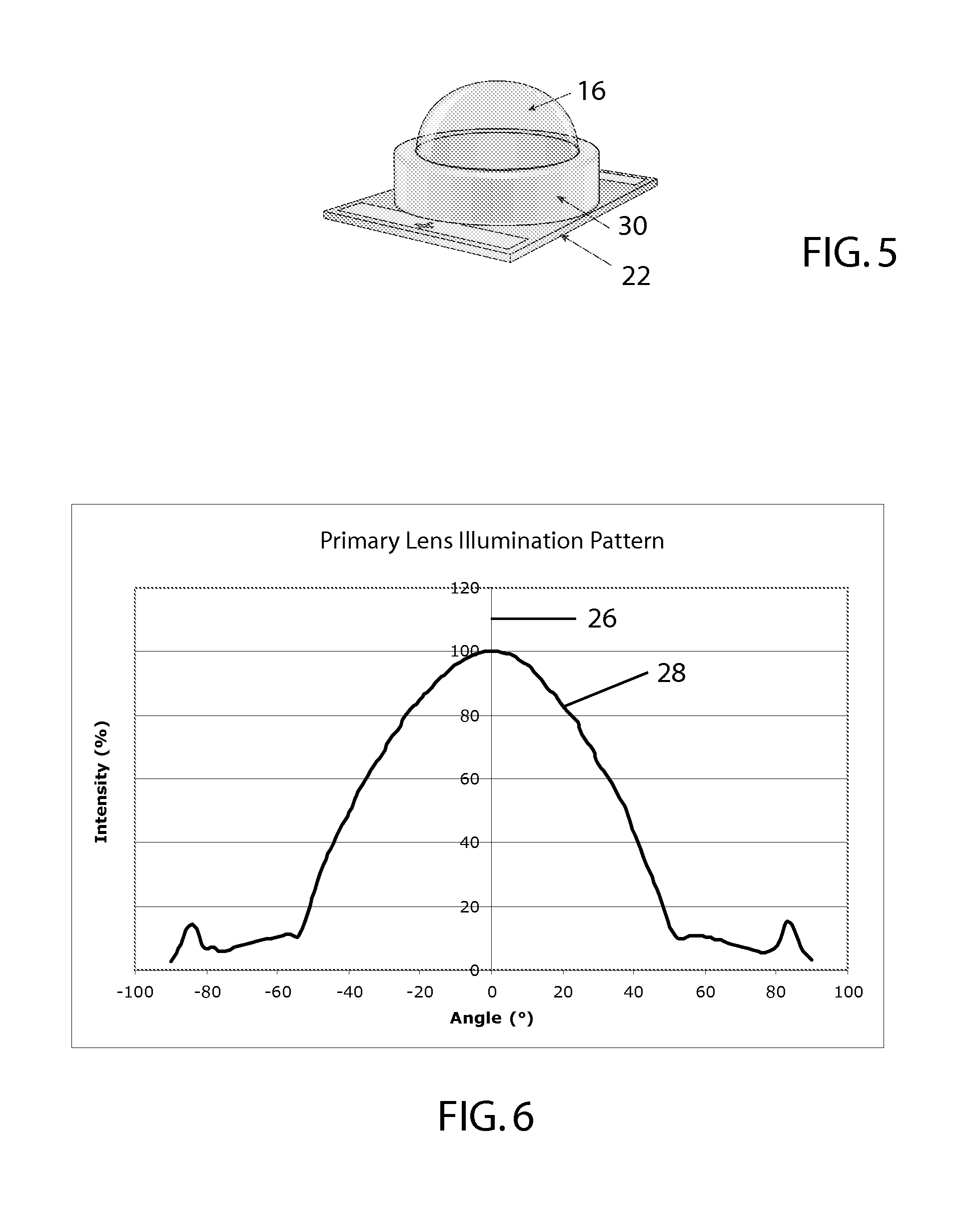
[0045]One embodiment of the inventive light-directing LED apparatus is shown in the figures as apparatus 10. Referring to FIGS. 1-5, apparatus 10 includes an LED light emitter 18 mounted a base 22. Light emitter 18 may include one of more LEDs. Light from emitter 18 passes out through a primary lens 16 positioned over light emitter 18. In apparatus 10, lens 16 is hemispherical and made of glass with a refractive index of between 1.4 and 1.6. Primary lens 16 can also be made of other suitable materials such as but not limited to optical-grade silicone. Primary lens 16 has a central axis 26 generally perpendicular to base 22 such that the light passing out through lens 16 from light emitter 18 produces an illumination pattern 28 (typical cross-section shown in FIG. 6) which is substantially rotationally symmetric around central axis 26. Apparatus 10 also includes a ring 30, preferably made of aluminum, around primary lens 10 on base 22 which serves to position lens 16 and to reflect s...


PUM


Abstract

LED apparatus for illumination toward a preferential side, including a light emitter having at least one LED on a base, a primary lens positioned over the light emitter and having a central axis, and a secondary lens placed with an inner surface surrounding the primary lens. The secondary lens has a base-adjacent lower end defining a main plane substantially perpendicular to the central axis, and a compound outer lens surface with a middle-region reference point defining a reference axis parallel to the central axis. The compound outer lens surface includes (A) a principal perimeter surface centered on the preferential side, the principal perimeter surface (a) projecting to a ridgeline subtending a substantial angle about the central axis, and (b) terminating inwardly at the ridgeline, (B) a middle region containing the reference point and having a concavity thereabout, and (C) a non-principal perimeter surface centered on the non-preferential side and adjoining the middle region and the principal perimeter surface.

Description

FIELD OF THE INVENTION[0001]The invention relates generally to the field of lighting systems and, more particularly, to apparatus for utilizing LED light sources for illuminating areas with a predefined pattern of light intensity.BACKGROUND OF THE INVENTION[0002]There is a need for lighting apparatus which is low-cost and energy efficient. LEDs (light-emitting diodes) provide light sources which are energy efficient, and advances in LED technology are providing even greater such efficiencies over time. In addition, one advantage of using LEDs as light sources is simply that the smaller packages of such sources translate into much lower material usage within fixtures containing such sources, thus yielding the attendant cost-efficiency. As the technology advances and the cost of LED packages is reduced, such material usage cost benefits will become more important.[0003]Typical applications for lighting systems are roadway and parking lot lighting in which there are performance require...

Claims


Application Information

Patent Timeline
Patent Type & Authority Applications(United States)
IPC IPC(8): F21S8/00
CPCF21V5/04F21V17/06F21V31/04F21W2131/103F21W2131/105Y10S362/80G02B3/02G02B27/0955H01L33/54G02B19/0014G02B19/0061F21Y2101/02F21Y2115/10
Inventor WILCOX, KURT S.
Owner IDEAL IND LIGHTING LLC
Why Eureka
Try Eureka