Light-directing lensing member with improved angled light distribution

a technology of angled light distribution and lensing member, which is applied in the field of light systems, can solve the problems of increased overall cost of led lighting using such lenses, difficult and expensive manufacturing, and low highly desirable performance of lenses, and achieve the effect of improving uniformity and improving the control of directed ligh

Active Publication Date: 2010-11-30
IDEAL IND LIGHTING LLC
View PDF114 Cites 95 Cited by
  • Summary
  • Abstract
  • Description
  • Claims
  • Application Information

AI Technical Summary

Benefits of technology

[0007]Another object of this invention is to provide a light-directing lensing member which maximizes the light directed toward a preferential side and minimizes light directed toward the opposite (non-preferential) side.
[0008]Another object of this invention is to provide a high-efficiency light-directing lensing member while satisfying requirements for minimizing trespass light.
[0010]Yet another object of this invention is to provide a light-directing lensing member which distributes light over an area on a preferential side, doing so with improved uniformity.
[0011]Another object of this invention is to provide a light-directing lensing member which directs a maximum amount of light to a preferential side, doing so with a single refraction to achieve improved control of the directed light.
[0014]This invention is an improved light-directing lensing member for directing light from an LED light emitter in a preferential-side off-axial direction with respect to the emitter axis. Such light distribution provides a significant widening of the preferential-side illumination angle with respect to the emitter axis and narrows the lateral illumination angle with respect to the emitter axis. Thus, the inventive lensing member provides a relatively elongated illumination pattern with farther light distribution on the preferential-side.
[0016]The major lens-portion outer surface has back, front and middle regions. The front region of the major lens-portion outer surface is centered on the front side of the lensing member and extends from the base end initially substantially orthogonally with respect to the main plane and then inwardly at a position and in a configuration such that the angle of incidence of light from the emitter thereon is less than the critical angle. The front region terminates inwardly at a ridgeline which is the set of major-lens-surface points farthest from the main plane. The back region of the major lens-portion outer surface is centered on the back side of the lensing member and extends from the base end at a position and in a configuration such that the angle of incidence of light from the emitter thereon is greater than the critical angle, thereby causing total internal reflection (TIR) of such light to significantly reduce the amount of light emanating from the back region, i.e., reducing the light directed toward the back side. It is preferred that the back region extends from the base end initially substantially orthogonally with respect to the main plane. The middle region is located around the emitter axis and contiguous with the front and back regions.

Problems solved by technology

However, such lenses fall short of highly desirable performance with respect to avoiding trespass lighting.
Some of such lenses are difficult and expensive to manufacture, which increases overall cost for LED lighting using such lenses.

Method used


Image

  • Light-directing lensing member with improved angled light distribution
  • Light-directing lensing member with improved angled light distribution
  • Light-directing lensing member with improved angled light distribution

Examples


Embodiment Construction

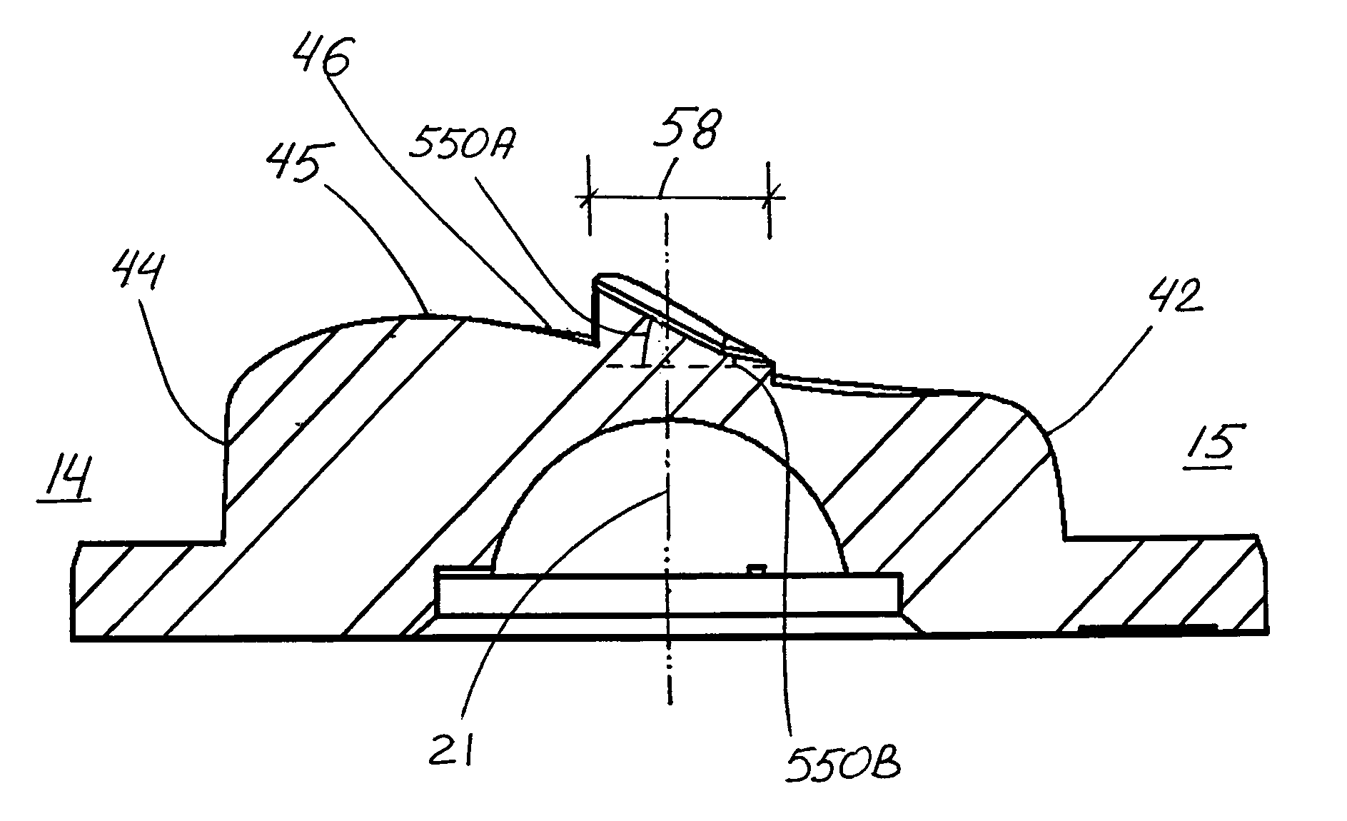
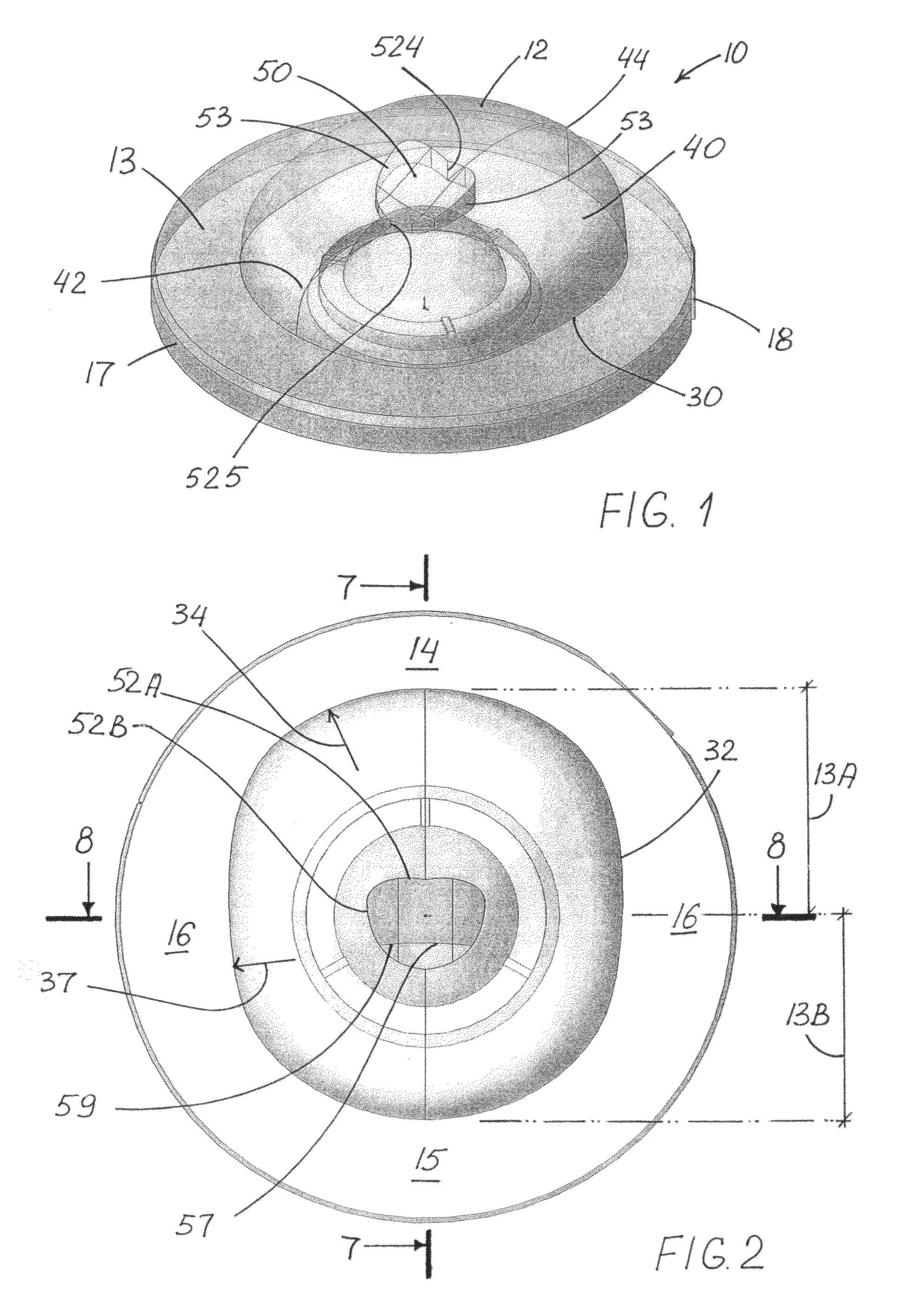
[0052]FIGS. 1-12 show preferred embodiment of an inventive light-directing lensing member 10 in accordance with this invention for off-axial preferential-side distribution of light from a light emitter 20 which has an emitter axis 21.

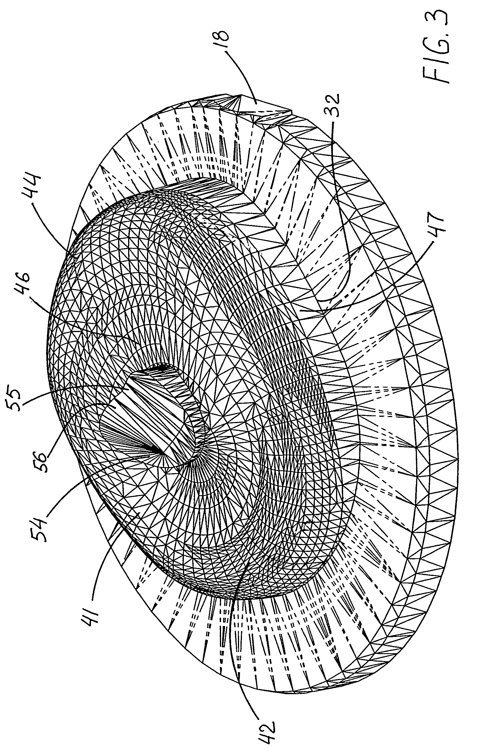
[0053]Lensing member 10 includes a base end 30 having a perimeter-loop line 32 defining a main plane 13 transverse emitter axis 21, and an outer surface 12 configured for refracting light from emitter 20 in a predominantly off-axis direction toward a preferential front side 14. Outer surface 12 includes a major lens-portion 40 and an axially-located minor lens-portion 50. Perimeter-loop line 32 has distances 13A and 13B from the emitter axis. As best seen in FIG. 2, distance 13A on preferential front side 14 is greater than distance 13B on a non-preferential back side 15.

[0054]Major lens-portion outer surface 41 has a back region 42, a front region 44 and a middle region 46. Front region 44 is centered on front side 14 and extends from base end 30 initi...


PUM


Abstract

A light-directing lensing member for off-axial preferential-side distribution of light from a light emitter having an emitter axis, including a base end with a perimeter-loop line defining a main plane transverse the emitter axis, and an outer surface configured for refracting light from the emitter in a predominantly off-axis direction toward the preferential side. The outer surface includes a major lens-portion and an axially-located minor lens-portion. The major lens portion outer surface has a front region centered on the front side, a back region centered on the back side, and a middle region around the emitter axis and contiguous with the front and back regions. The minor lens-portion has a surrounding-loop surface extending from the middle region transverse the main plane and terminating at an end surface configured to direct substantially axially-parallel light from the emitter in off-axis direction toward the preferential side.

Description

FIELD OF THE INVENTION[0001]The invention relates generally to the field of lighting systems and, more particularly, to apparatus for utilizing LED light sources for illuminating areas with predefined patterns of light intensity.BACKGROUND OF THE INVENTION[0002]There is a continuing need for lighting apparatus which is low-cost and energy-efficient. LEDs (light-emitting diodes) provide light sources which are energy-efficient, and advances in LED technology are providing even greater efficiencies over time.[0003]Some of the newer applications for LED-based lighting systems are roadway, street and parking-lot lighting. In such applications, there are desired performance characteristics with respect to light distribution. More specifically, it is desirable that certain regions about a light fixture be illuminated, while certain neighboring regions are essentially non-illuminated. Along roadways and in parking lots, there is a need to be able to direct light in a particular preferentia...

Claims


Application Information

Patent Timeline
Patent Type & Authority Patents(United States)
IPC IPC(8): F21V5/04F21V5/08
CPCF21S8/081F21V5/04F21V5/08F21V7/0091G02B19/0071G02B19/0028G02B19/0061F21W2131/103F21Y2101/02F21Y2115/10F21K9/69
Inventor WILCOX, KURT S.STROM, CHRIS
Owner IDEAL IND LIGHTING LLC
Why Eureka
Try Eureka