Ball screw device having circulating device background of the invention

a technology of circulating device and ball screw, which is applied in the direction of mechanical equipment, gearing, hoisting equipment, etc., can solve the problems of affecting the rotational speed the distorted corner area or the bent portion of the tubular element, and the inability of balls or rollers or bearings to suitably move through the tubular element, so as to facilitate the rotational movement of the ball nut and the effect of effective and smooth receiving and guiding

Active Publication Date: 2011-05-03
HIWIN TECH
View PDF12 Cites 10 Cited by
  • Summary
  • Abstract
  • Description
  • Claims
  • Application Information

AI Technical Summary

Benefits of technology

[0014]The primary objective of the present invention is to provide a ball screw device including a circulating device for effectively and smoothly receiving and guiding the balls or the bearing members to move relative to the ball nut and the screw shaft, and for facilitating the rotational movement of the ball nut and the screw shaft relative to each other in great rotational speeds.
[0015]The other objective of the present invention is to provide a ball screw device including a circulating device having a structure for allowing the circulating device to be easily and quickly and precisely formed or made with the molding or mold-injection procedures and to be easily and quickly and readily removed or disengaged from the mold devices.
[0016]In accordance with one aspect of the invention, there is provided a ball screw device comprising a screw shaft including an outer thread formed thereon, a ball nut including a bore formed therein for receiving the screw shaft, and including an inner thread formed therein for forming a helical raceway between the ball nut and the screw shaft, the ball nut including two openings formed therein and communicating with the bore of the ball nut, a number of bearing members received in the helical raceway between the ball nut and the screw shaft for facilitating a rotating movement between the ball nut and the screw shaft, and a circulating device including an elongate member having two end blocks for engaging into the openings of the ball nut, the elongate member including a passage formed therein and directed toward the inner thread of the ball nut and the outer thread of the screw shaft for receiving the bearing members, the circulating device includes a housing member and a casing member each including a portion of the passage of the elongate member formed therein, for allowing the passage of the elongate member to be opened and exposed in the housing member and the casing member and for allowing the housing member and the casing member to be easily and precisely formed with molding procedures.

Problems solved by technology

However, the tubular elements are required to be bent from a longitudinal tubular member, and the corner areas or the bent portions of the tubular elements may be distorted such that the balls or the rollers or the bearing members may not suitably move through the tubular elements.
However, similarly, the return tubes are also required to be bent from a longitudinal tubular member, and the corner areas or the bent portions of the return tubes may be distorted such that the balls or the rollers or the bearing members may not suitably move through the return tubes.
However, similarly, the transfer tubes are also required to be bent from a longitudinal tubular member, and the corner areas or the bent portions of the transfer tubes may be distorted such that the balls or the rollers or the bearing members may not suitably move through the transfer tubes.
However, similarly, the circulation tubes are also required to be bent from a longitudinal tubular member, and the corner areas or the bent portions of the circulation tubes may be distorted such that the balls or the rollers or the bearing members may not suitably move through the circulation tubes.

Method used


Image

  • Ball screw device having circulating device background of the invention
  • Ball screw device having circulating device background of the invention
  • Ball screw device having circulating device background of the invention

Examples


Embodiment Construction

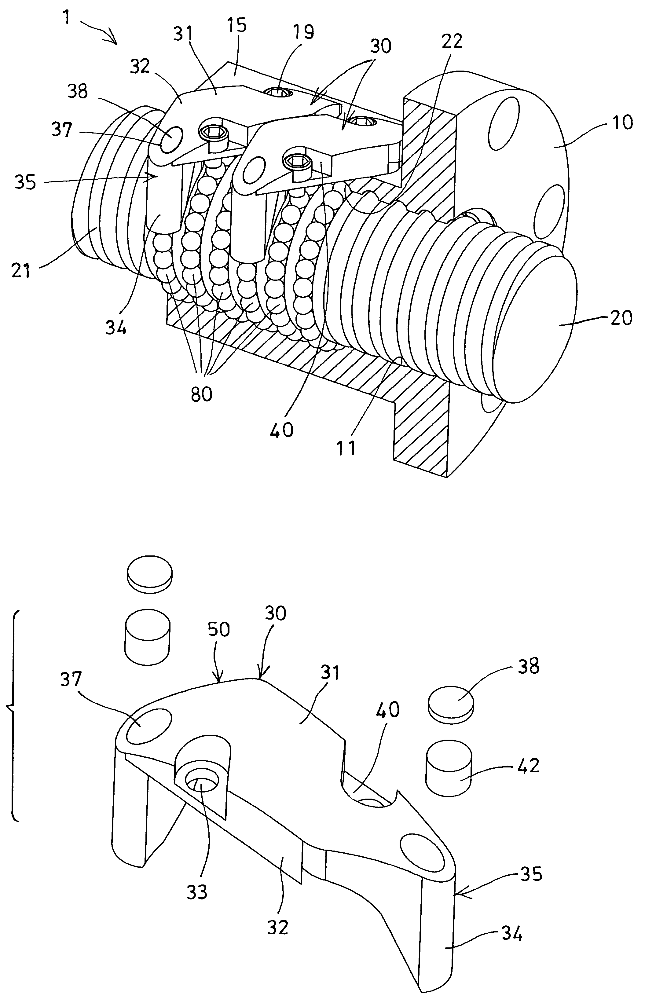
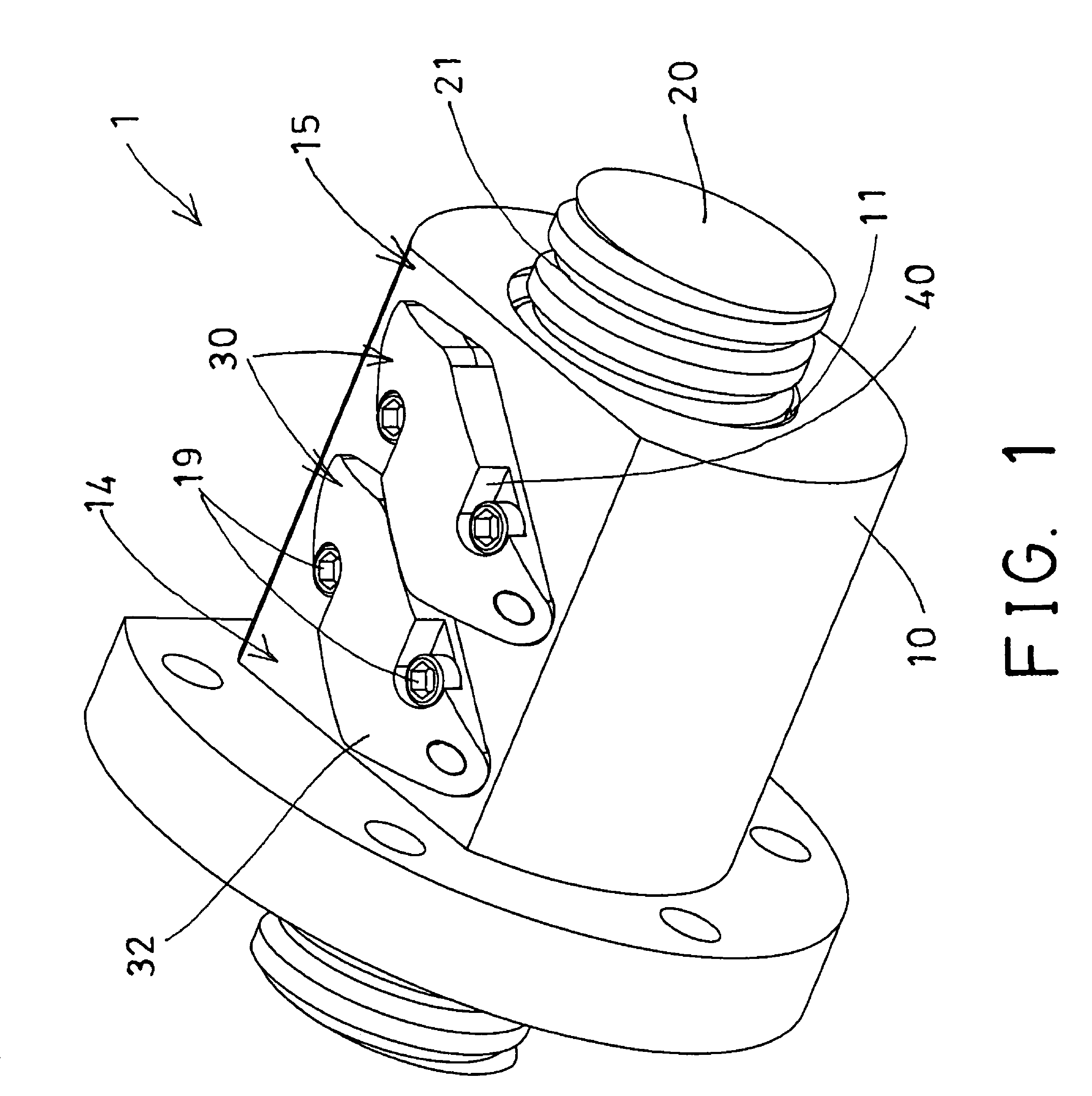
[0032]Referring to the drawings, and initially to FIGS. 1-3, a ball screw device 1 in accordance with the present invention comprises an outer ball nut 10 including a bore 11 formed therein for receiving a typical screw shaft 20 and having an inner thread 12 formed therein for threading with or for engaging with an outer thread 21 of the screw shaft 20 and for allowing the ball nut 10 to be moved along the screw shaft 20, or for allowing the screw shaft 20 to be rotated and moved relative to the ball nut 10. The threading engagement and / or the rotational engagement between the ball nut 10 and the screw shaft 20 is typical and will not be described in further details.

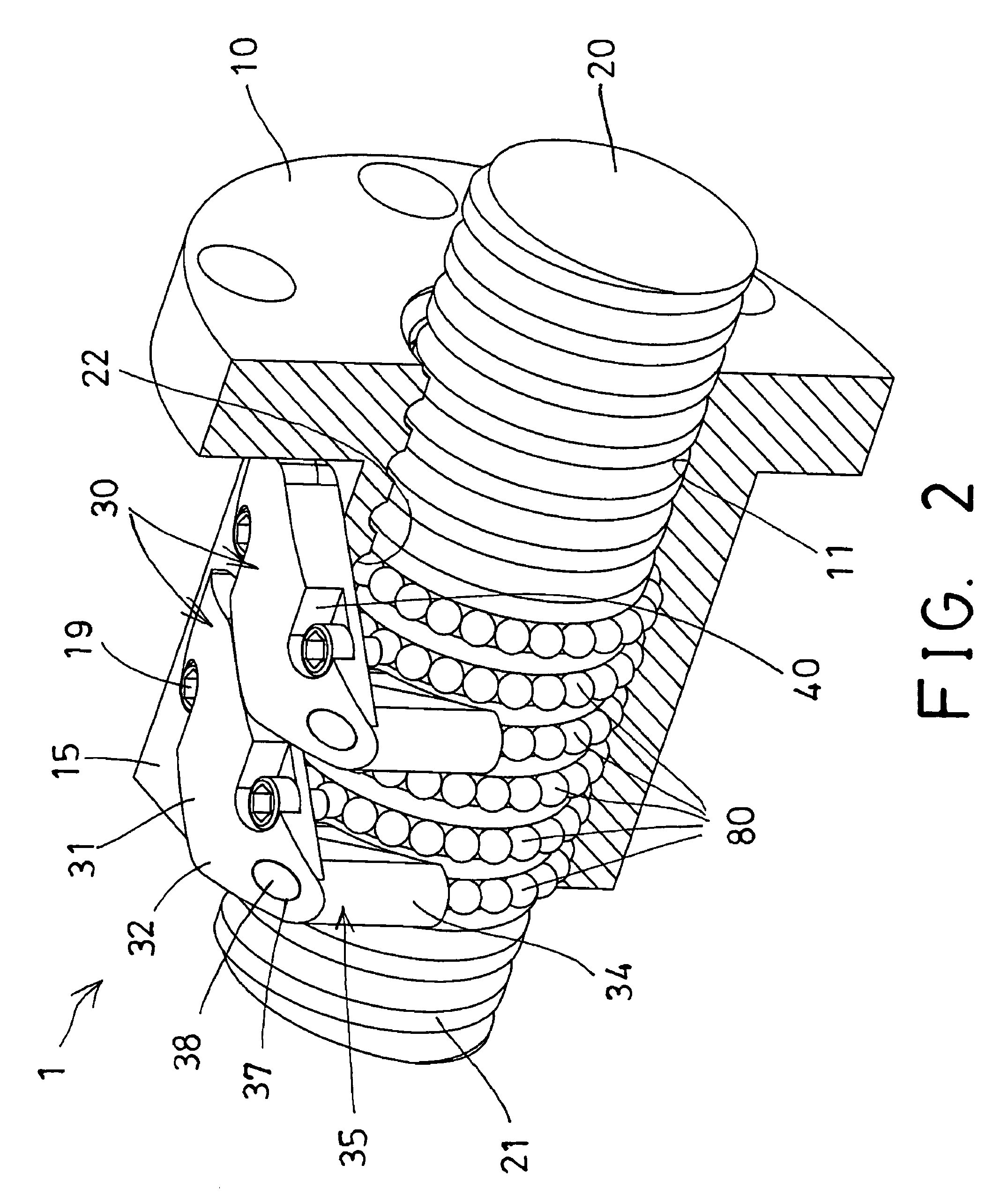
[0033]A multiple turn, helical raceway 22 will be formed between the ball nut 10 and the screw shaft 20 (FIG. 2) for rotatably and / or movably receiving one or more groups of balls or rollers or rolling or ball bearing members 80 (FIGS. 2, 3) therein which may facilitate the rotating movement of the ball nut 10 relative t...


PUM


Abstract

A ball screw device includes a screw shaft rotatably engaged with a ball nut, and a number of bearing members received between the ball nut and the screw shaft, and a circulating device for circulating the bearing members, the circulating device includes an elongate member having two end blocks for engaging into the ball nut and having a passage for receiving the bearing members, and includes a housing member and a casing member each having a portion of the passage of the elongate member for allowing the passage of the elongate member to be opened and exposed and for allowing the housing member and the casing member to be formed with molding procedures.

Description

BACKGROUND OF THE INVENTION[0001]1. Field of the Invention[0002]The present invention relates to a ball screw device, and more particularly to a ball screw device having a circulating device for effectively and smoothly receiving and guiding the balls or the rollers or the bearing members to move relative to the ball nut and the screw shaft, and for facilitating the rotational movement of the ball nut and the screw shaft relative to each other in great rotational speeds.[0003]2. Description of the Prior Art[0004]Typical ball screw devices comprise a ball nut rotatably and / or moveably engaged onto a screw shaft, and normally arranged to allow the ball nut to be rotated and / or moved relative to the screw shaft in great rotational speeds. For allowing the ball nut to be smoothly rotated and moved relative to the screw shaft, a suitable bearing device or lubricating structure is further required to be provided and engaged between the ball nut and the screw shaft, for facilitating the ro...

Claims


Application Information

Patent Timeline
Patent Type & Authority Patents(United States)
IPC IPC(8): F16H25/22
CPCF16H25/2214Y10T74/18744Y10T74/19749Y10T74/19767
Inventor CHEN, YAN YUCHIU, YUEH LING
Owner HIWIN TECH
Why Eureka
Try Eureka