Ball screw device having a ball guide member

a technology of ball nut and guide member, which is applied in the direction of gearing elements, hoisting equipment, gearing, etc., can solve the problems that the ball or the ball train cannot be effectively guided to move into the corresponding axial return passage, and achieves the effect of effective and smooth receiving and guiding, facilitating the rotational movement of the ball nut, and great rotational speed

Active Publication Date: 2009-04-28
HIWIN TECH
View PDF16 Cites 26 Cited by
  • Summary
  • Abstract
  • Description
  • Claims
  • Application Information

AI Technical Summary

Benefits of technology

[0009]The primary objective of the present invention is to provide a ball screw device including an inserted ball guide member for effectively and smoothly receiving and guiding the balls or the bearing members to move relative to the ball nut and the screw shaft, and for facilitating the rotational movement of the ball nut and the screw shaft relative to each other in great rotational speeds.
[0010]The other objective of the present invention is to provide a ball screw device including an inserted ball guide member having two curved pathways for forming two separated endless ball rolling passages in the ball nut and for smoothly receiving and guiding two groups of bearing members.
[0012]In accordance with one aspect of the invention, there is provided a ball screw device comprising a ball nut including a bore formed therein and having an inner thread formed therein and defined by a number of helical groove portions, the ball nut including at least one opening formed therein and communicating with the bore thereof, and the ball nut including a first channel and a second channel formed therein and communicating with the opening thereof, a screw shaft rotatably engaged into the bore of the ball nut, and including an outer thread formed thereon and defined by a number of helical groove portions for threading with the inner thread of the ball nut and for allowing the ball nut to be rotated and moved relative to the screw shaft, at least one guide member engaged into the opening of the ball nut, and including two curved pathways formed therein and communicating the first and the second channels with the helical groove portions of the ball nut respectively to form two separated endless ball rolling passages in the ball nut respectively, and two groups of bearing members engaged in the two separated endless ball rolling passages in the ball nut respectively for engaging between the ball nut and the screw shaft and for facilitating a movement of the ball nut relative to the screw shaft.

Problems solved by technology

However, due to manufacturing or machining considerations, the ball return channels of the inbuilt plastic insert should be exposed and may not be deeply formed in the inbuilt plastic insert, such that the balls or the ball train may not be effectively guided to move into the corresponding axial return passages that are formed and provided in the ball nut.
However, there in only one ball return passage or endless ball train guiding passage may be formed and provided between the ball nut and the ball screw and between the two end caps, such that only a limited number of the balls or the ball train may be provided and engaged between the ball nut and the ball screw.

Method used


Image

  • Ball screw device having a ball guide member
  • Ball screw device having a ball guide member
  • Ball screw device having a ball guide member

Examples


Embodiment Construction

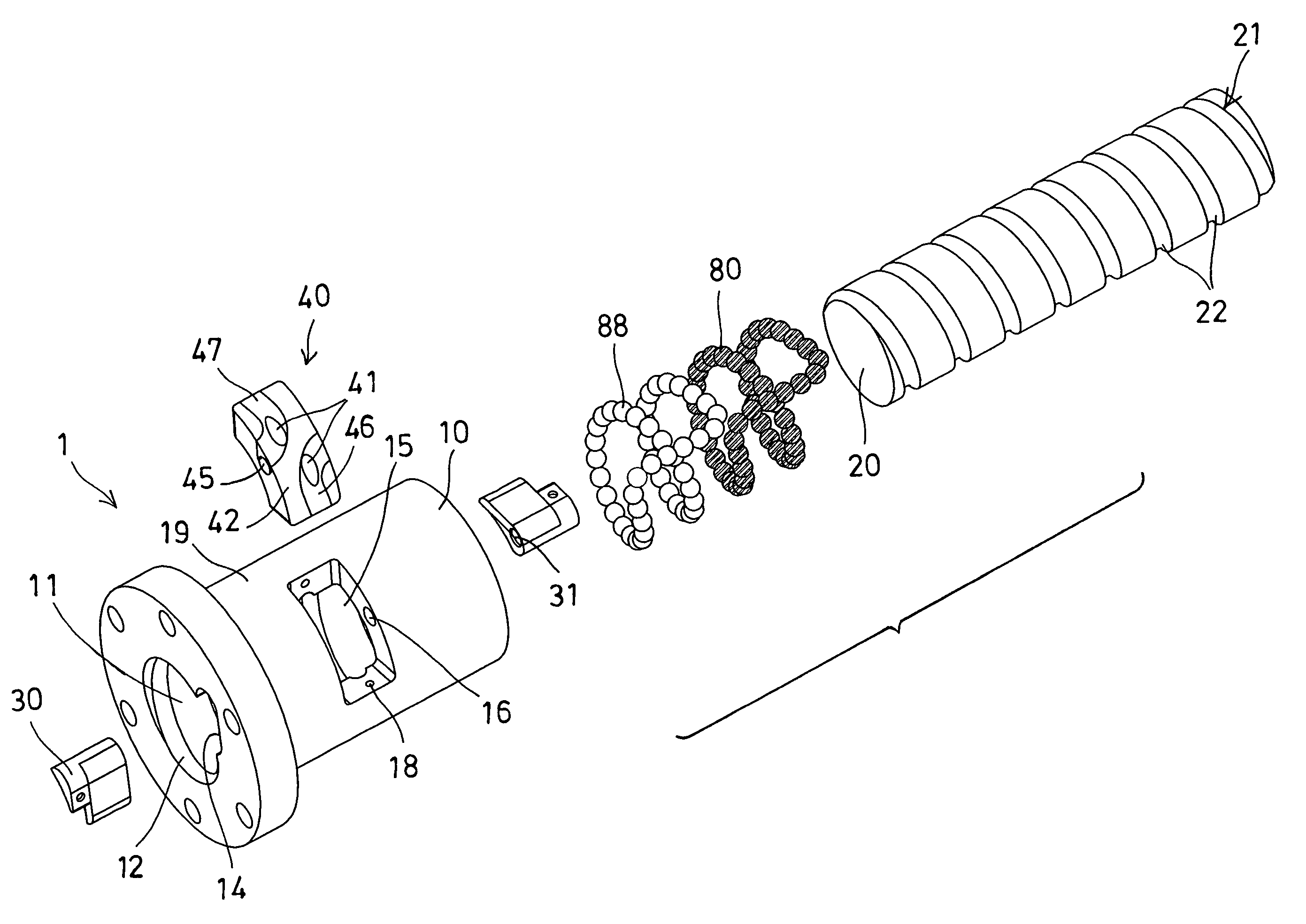
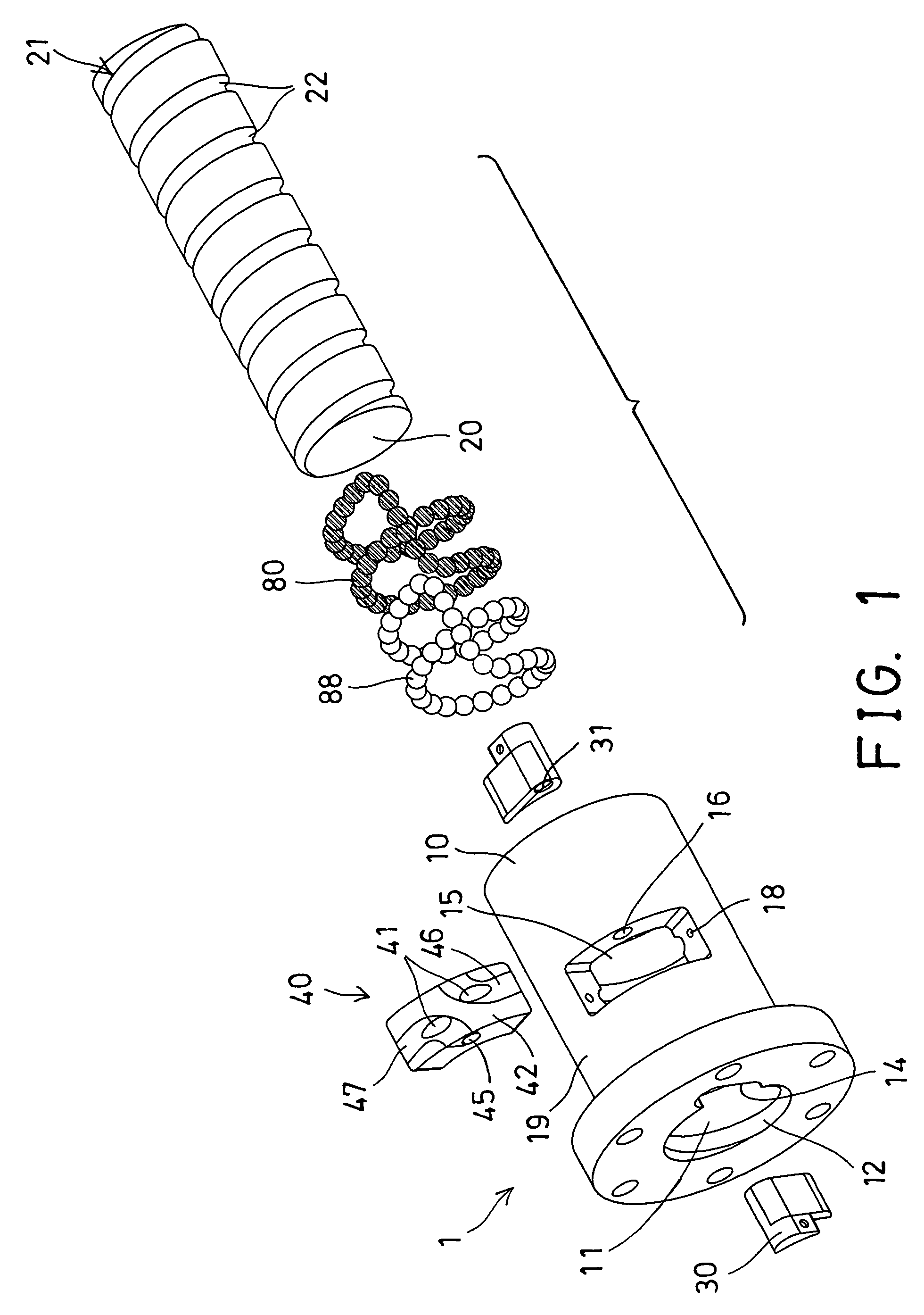
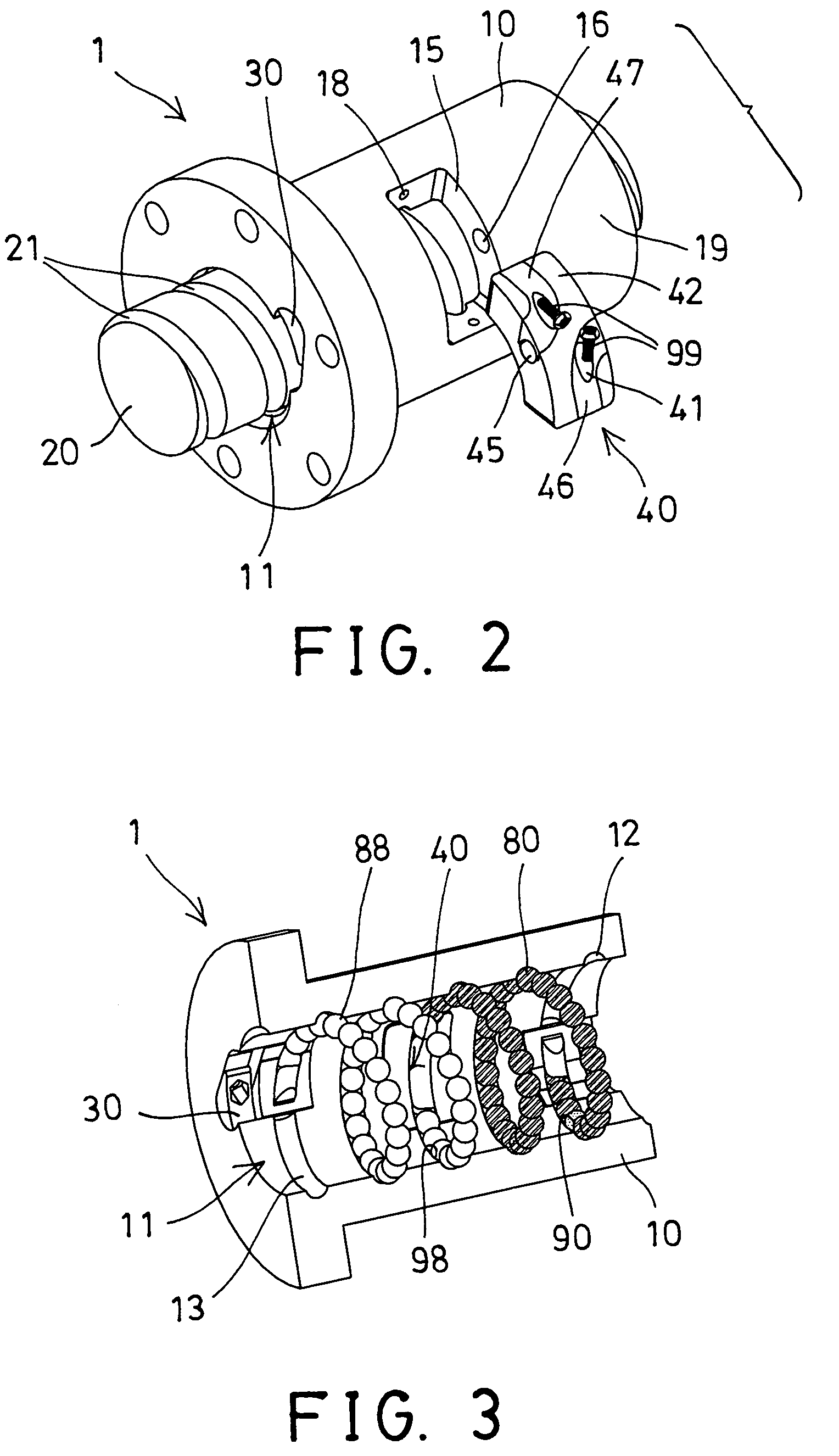
[0029]Referring to the drawings, and initially to FIGS. 1-5, a ball screw device 1 in accordance with the present invention comprises an outer ball nut 10 including a bore 11 formed therein and having an inner thread 12 formed therein and defined by a number of peripheral and helical groove portions 13 (FIGS. 3, 4), for threading with an outer thread 21 of a screw shaft 20, and thus for allowing the ball nut 10 to be moved along the screw shaft 20, or for allowing the screw shaft 20 to be rotated and moved relative to the ball nut 10.

[0030]The screw shaft 20 also includes a number of peripheral and helical groove portions 22 formed therein for forming or defining the outer thread 21 thereof, and for forming a multiple turn, helical raceway and for rotatably and / or movably receiving one or more groups of balls or rollers or rolling or ball bearing members 80, 88 therein which may facilitate the rotating movement of the ball nut 10 relative to the screw shaft 20 when the screw shaft 2...


PUM


Abstract

A ball screw device includes a screw shaft threaded with a ball nut which has two channels and an opening, a guide member is engaged into the opening of the ball nut and has two curved pathways communicating with the channels to form two separated endless ball rolling passages in the ball nut, and two groups of bearing members are engaged in the two separated endless ball rolling passages for facilitating a movement of the ball nut relative to the screw shaft. The guide member includes two bars for enclosing the curved pathways of the guide member, and the bars each have a curved recess for forming the curved pathways of the guide member and for allowing the guide member to be easily manufactured.

Description

BACKGROUND OF THE INVENTION[0001]1. Field of the Invention[0002]The present invention relates to a ball screw device, and more particularly to a ball screw device having an inserted ball guide member for effectively and smoothly receiving and guiding the balls or the bearing members to move relative to the ball nut and the screw shaft, and thus for facilitating the rotational movement of the ball nut and the screw shaft relative to each other in great rotational speeds.[0003]2. Description of the Prior Art[0004]Typical ball screw devices comprise a ball nut rotatably and / or moveably engaged onto a screw shaft, and normally arranged to allow the ball nut to be rotated and / or moved relative to the screw shaft in great rotational speeds. For allowing the ball nut to be smoothly rotated and moved relative to the screw shaft, a suitable bearing device or lubricating structure is further required to be provided and engaged between the ball nut and the screw shaft, for facilitating the rot...

Claims


Application Information

Patent Timeline
Patent Type & Authority Patents(United States)
IPC IPC(8): F16H1/24
CPCF16H25/2214F16H25/2219Y10T74/19767Y10T74/19753Y10T74/19772
Inventor LIAO, CHI MENGCHEN, YAN YU
Owner HIWIN TECH
Why Eureka
Try Eureka