Writing implement

a technology of implements and cylinders, applied in the direction of writing connectors, nibs, printing, etc., can solve the problems of poor air tightness, damage to the ring-shaped projection, staining the hand, etc., and achieve the effect of preventing damage to the airtight seal portion, and avoiding the effect of pressurizing the air inside the cap

Active Publication Date: 2011-05-17
THE PILOT INK CO LTD
View PDF23 Cites 1 Cited by
  • Summary
  • Abstract
  • Description
  • Claims
  • Application Information

AI Technical Summary

Benefits of technology

[0009]In view of the above-described problems, the invention aims at solving the problems found in the above-mentioned conventional structure. That is, it is an object of the invention to provide a writing implement in which: when mounting a cap, a pen tip can be prevented from contacting with an airtight seal portion formed in the cap to thereby not only prevent damage to the airtight seal portion of the cap and ink adhesion to the airtight seal portion but also prevent damage to an airtight seal portion formed in a barrel; even when the cap is mounted suddenly, pressurization of the air in the inside of the cap can be avoided sufficiently; and, even when the cap is removed suddenly, decompression of the air in the interior of the inner cap can be sufficiently prevented.

Problems solved by technology

With use of the cap mounting structure disclosed in the above-mentioned JP-UM-A-2-144488, there is a fear that, when the cap is mounted, the pen tip can be contacted with the ring-shaped projection (airtight seal portion) on the end face of the inner cap to thereby cause ink to adhere to the ring-shaped projection and thus stain the ring-shaped projection or to thereby damage the ring-shaped projection and thus cause poor air tightness.
Especially, if the ink adheres to the ring-shaped projection, there is a fear that the ink adhered to the ring-shaped projection, as the cap is mounted onto the barrel, can adhere to the barrel and thus, when a user holds the barrel with a hand, the ink can adhere to the hand to thereby stain the hand.
Also, with use of the cap mounting structure disclosed in the JP-UM-A-2-144488, since the airtight seal portion is formed in the front end face of the barrel and the airtight seal portion is exposed to the outside, there is a fear that the airtight seal portion can be damaged by accident to thereby cause a poor airtight condition.
However, since the clearance between the outer surface of the barrel and the inner surface of the cap cannot be set so large actually, there is a fear that, when the cap mounting operation is performed suddenly, the pressure air (compressed air) within the cap cannot be sufficiently discharged to the outside, thereby causing the pressure air to flow into the inside of the barrel; or, when a cap removing operation is carried out suddenly, the air existing within the cap can be decompressed, whereby the ink can leak out from the pen point side.

Method used


Image

  • Writing implement
  • Writing implement
  • Writing implement

Examples


embodiments

[0104]Now, description will be given below in order of the embodiments of a writing implement 1 according to the invention with reference to the accompanying drawings.

first embodiment

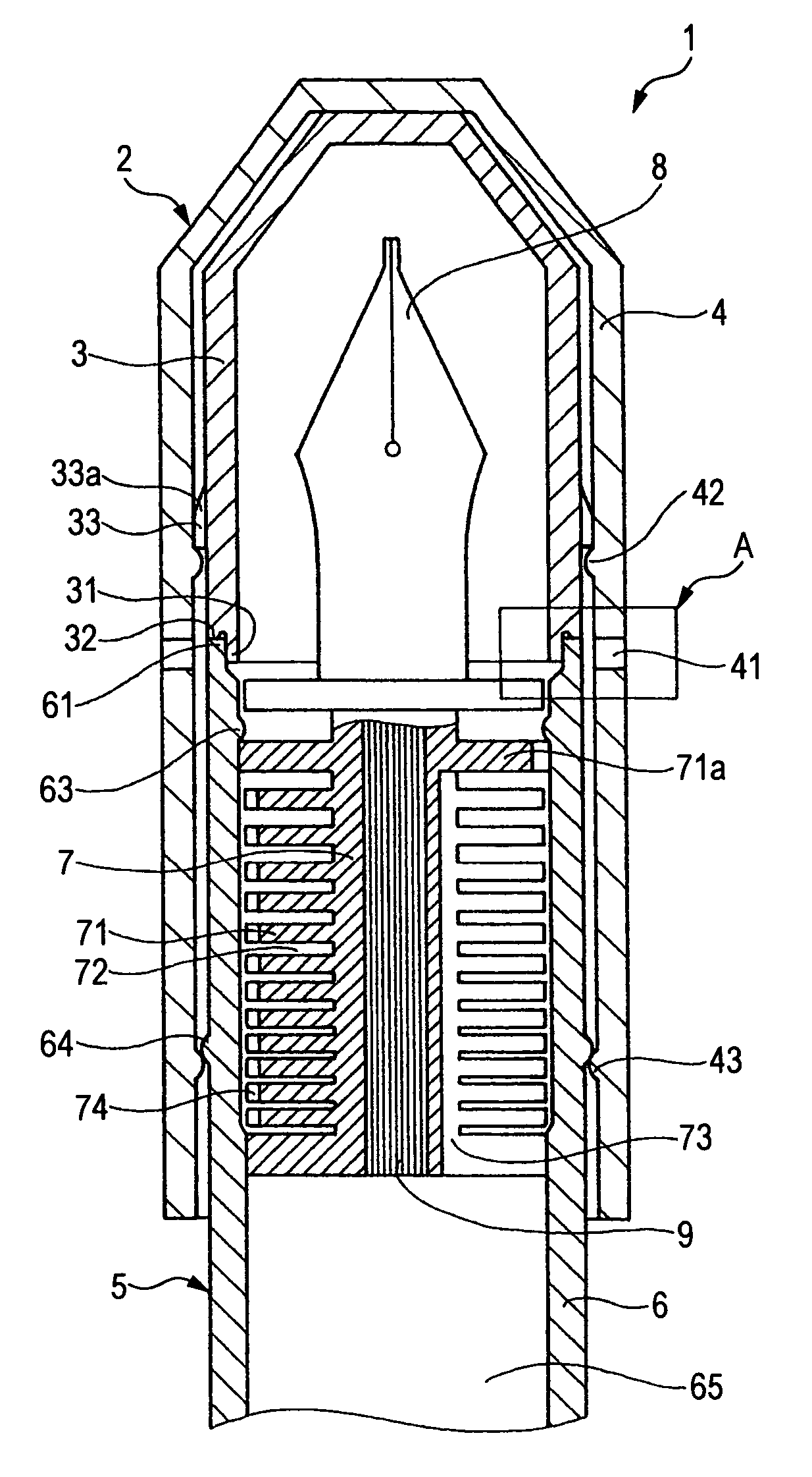
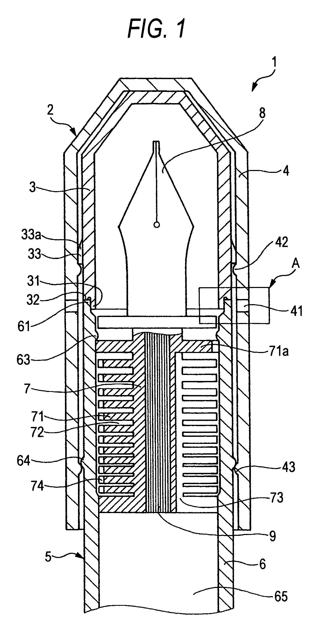
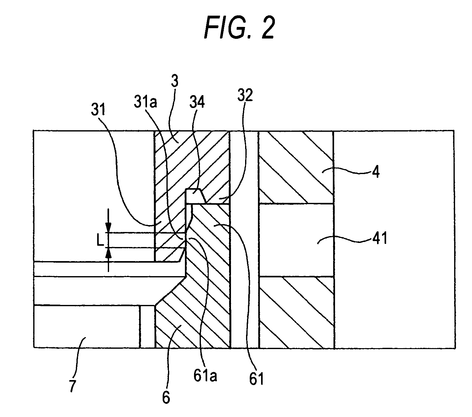
[0105]FIGS. 1 to 4 show a first embodiment of a writing implement 1 according to the invention. Specifically, FIG. 1 shows a state of the writing implement 1 according to the first embodiment in which a cap is mounted. FIG. 2 is an enlarged view of the A portion of FIG. 1. FIG. 3 shows a cap 2 shown in FIG. 1. FIG. 4 shows the pen tip 8 side of a writing implement main body 5 shown in FIG. 1. The present embodiment comprises a cap 2 and a writing implement main body 5 structured such that the cap 2 can be removably mounted on the pen tip 8 side thereof.

(Cap)

[0106]Now, description will be given below of the cap 2 according to the present embodiment. The cap 2 comprises an inner cap 3 and an outer cap 4 with the inner cap 3 fixed to the inner surface thereof, the outer cap 4 being made of other part than the inner cap 3.

(Inner Cap)

[0107]The inner cap 3 is formed as a cylindrical-shaped bottomed shell member with its front end closed and its rear end opened. That is, the inner cap 3 ha...

second embodiment

[0124]Now, FIG. 5 shows a second embodiment according to the invention.

[0125]In the second embodiment, the ventilating hole 41 is formed in the side wall of the outer cap 4 existing in front of the rear end shell portion 31 of the inner cap 3. Thanks to the ventilating hole 41, the interior of the inner cap 3 and the outside (open air) of the outer cap 4 are allowed to communicate with each other through a clearance and a ventilating groove 33a respectively formed between the outer surface of the inner cap 3 and the inner surface of the outer cap 4. Also, according to the second embodiment, on the outer surface of the outer cap 4, there is provided a clip 44, while the ventilating hole 41 is opened inwardly in the radial direction of the clip 44. This makes it difficult to see the ventilating hole 41 from the outside, thereby being able to enhance the outer appearance of the writing implement. By the way, the remaining structures and operations of the second embodiment are similar t...


PUM


Abstract

The outer surface of an inner cap 3 is fixedly secured to the inner surface of an outer cap 4. In the opened end portion of the inner cap 3, there is formed a rear end shell portion 31 which projects backwardly. On the outer peripheral surface of the rear end shell portion 31, there is provided a ring-shaped outward facing seal portion. In the front end portion of a barrel 6, there is formed a front end shell portion 61 projecting forwardly. In the inner peripheral surface of the front end shell portion 61, there is formed a ring-shaped inward facing seal portion. When a cap 2 is mounted on the pen tip 8 side of the barrel 6, the outward facing seal portion can be closely contacted with the inward facing seal portion in the radial direction.

Description

BACKGROUND OF THE INVENTION[0001]1. Field of the Invention[0002]The present invention relates to a writing implement. In this invention, the term [front] means a closed side of a cap and a pen tip side of the main body of the writing implement, while the term [rear] means an opened side of the cap and an ink tank side of the main body of the writing implement.[0003]2. Description of the Background Art[0004]Referring to a writing implement of this type, conventionally, in Japanese Utility Model Unexamined Publication No. JP-UM-A-2-144488, there is disclosed a cap mounting structure of the writing implement, in which the cap including an inner cap therein is mounted on a leading end portion of a barrel including a pen tip to thereby keep interior of the cap in air tight manner, wherein the inner cap is formed of soft elastic resin material and a ring-shaped projection is provided on the leading end face of the barrel and / or the end face portion of the inner cap which, when the cap is ...

Claims


Application Information

Patent Timeline
Patent Type & Authority Patents(United States)
IPC IPC(8): B43K23/12
CPCB43K23/12B43K1/00B43K5/02B43K7/02B43K23/124
Inventor IWATA, HISASHI
Owner THE PILOT INK CO LTD
Why Eureka
Try Eureka