Power supply apparatus

a power supply and equipment technology, applied in the direction of emergency power supply arrangement, dc-ac conversion without reversal, pulse technique, etc., can solve the problems of reducing the efficiency of the filter for filtering output wave, and reducing the total efficiency of the whole unit, so as to reduce the loss, increase the voltage compensation, and reduce the voltage compensation

Inactive Publication Date: 2011-06-21
MITSUBISHI ELECTRIC CORP
View PDF20 Cites 3 Cited by
  • Summary
  • Abstract
  • Description
  • Claims
  • Application Information

AI Technical Summary

Benefits of technology

In an uninterrupted power supply unit according to the invention, there are advantages in which a combination of the single phase inverters enables increasing voltage compensation and decreasing voltage compensation, thereby achieving voltage compensation at a time of power failure and supplying a stabilized voltage to the load in any voltage condition.

Problems solved by technology

As a result, the current is always passed through semiconductors even in the normal voltage condition, causing to give rise to a loss of power, to reduce a total efficiency of the whole unit, and to upsize a cooling device.
There also exists a problem that since an output of the inverter requires PWM controlled-rectangular wave, a filter for filtering the output wave must be upsized.
In such configuration, since the step-up transformer is required to have a function for filtering a rectangular voltage generated in the inverter, and to transmit a voltage having a commercial frequency, the problem exists in that the product of voltage and time, that is, flux volume, is required to be a large value, resulting in the system of upsized and expensive construction.

Method used


Image

  • Power supply apparatus
  • Power supply apparatus
  • Power supply apparatus

Examples


embodiment 1

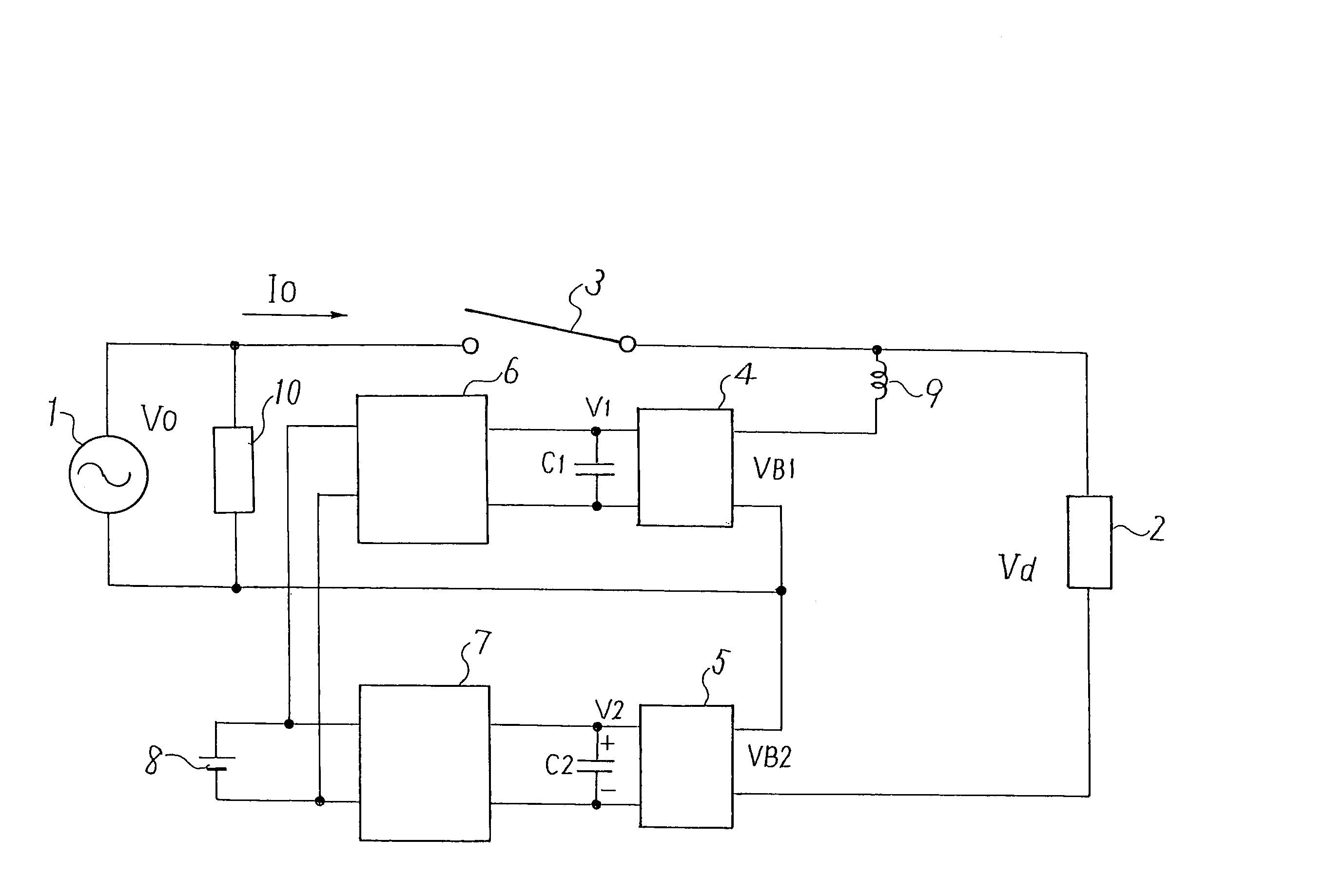
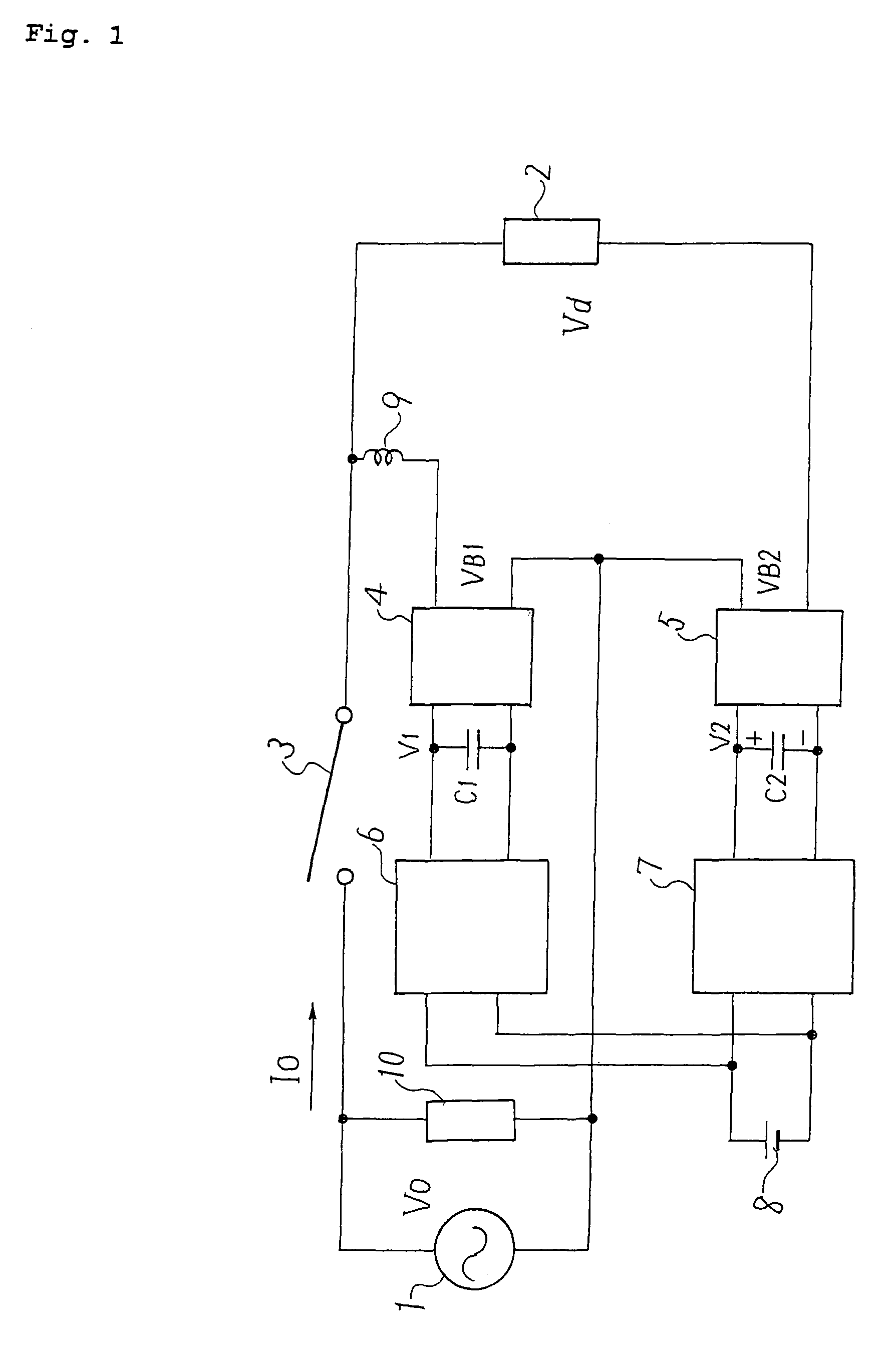
FIG. 1 shows a schematic circuit diagram of an uninterrupted power supply unit according to Embodiment 1 of the present invention. In FIG. 1, a power source 1 is a commercial alternating current source normally having a system voltage V0, directly supplying a power to the load 2 via a straight-forward switch 3 which is a mechanical switch such as a relay. The load 2 is connected to a first single phase inverter 4 of which AC side terminals are connected in parallel with the load 2 and a second single phase inverter 5 of which AC side terminals are connected in series with the load 2. The DC side terminals of the first single phase inverter 4 is connected to a DC-DC converter 6 through a capacitor C1, and the DC side terminals of the second single phase inverter 5 is connected to a DC-DC converter 7 through a capacitor C2. The other side terminals of the DC-DC converters 6, 7 are connected to an energy storage device such as a battery 8 in common. A combination of the DC-DC converter...

embodiment 2

FIG. 6 shows a modified example of the embodiment 1 according to the embodiment 2 of this invention, and is same with FIG. 1 except that the second single phase inverter 5 is directly connected to the battery 8. The voltage compensation operation that is the voltage increasing / decreasing operation is identical to that in the embodiment 1. By taking this configuration, the voltage V2 inputted to the second single phase inverter 5 becomes constant, and although it is not possible to set the ratio of V1:V2 finely, it becomes possible to manufacture in simpler and inexpensive construction, because of an omission of DC-DC converter 7.

embodiment 3

FIG. 7 shows the modified example of the uninterrupted power supply unit according to the voltage increasing / decreasing operation of the present invention. Although, in FIG. 1 and FIG. 6, the second single phase inverter 5 is connected between the first single phase inverter 4 and the load 2, the second single phase inverter 5 in FIG. 7 is connected between the system power source 1 and the first single phase inverter 4. In this configuration, the following operation differs from that of the above embodiments.

First, in the mode in which the relay current is controlled to zero when the system voltage dropped and the relay got into a cutting-off operation, only the first single phase inverter 4 is used for PWM control in the previous embodiments, but in this embodiment, the total of the output voltages of both the first single phase inverter 4 and the second single phase inverter 5 are applied to the relay to finely control the relay current by the individual control of each output vo...


PUM


Abstract

An uninterrupted power supply unit is provided with a straightforward switch connected between a power source and a load to supply or interrupt a power to a system. The combination of the outputs from two kinds of single phase inverters enables compensating for a variation in the system voltage in the normal condition and to supply a predetermined voltage to the load after decreasing in the system voltage and opening of a straight forward switch.

Description

TECHNICAL FIELDThe present invention relates to a power supply apparatus, in particular, to a power supply apparatus having a straightforward switch connected in series with a system.BACKGROUND ARTHeretofore, a variety of circuitry of power supply apparatuses have been proposed as disclosed in, for example, Japanese Patent Laid-open Publication JP 01-222635 (referred to as Patent Document 1) and Japanese Patent Laid-open Publication JP 08-223822 (referred to as Patent Document 2).One conventional uninterrupted power supply unit shown in Patent Document 1 is provided with a constant voltage / constant frequency power supply unit (CVCF) in which an alternative current (AC) input voltage is once converted into a direct current (DC) voltage, then the converted DC voltage is reversely converted into the AC voltage again, and a bypass circuit comprising semiconductor switches which bypass the CVCF. Such power supply unit is constituted so that in a normal voltage condition as well as in a d...

Claims


Application Information

Patent Timeline
Patent Type & Authority Patents(United States)
IPC IPC(8): H02J1/12H02J3/18H02J9/06H02M7/48H02M7/49
CPCH02J3/1814H02M7/49H02J9/062Y02E40/18Y02E40/10
Inventor YAMADA, MASAKIIWATA, AKIHIKOHATAKEYAMA, YOSHIHIRO
Owner MITSUBISHI ELECTRIC CORP
Why Eureka
Try Eureka