Imaging apparatus with a rotatable monitor

a technology of rotatable monitors and imaging apparatuses, which is applied in the field of imaging apparatuses, can solve the problems of reducing portability and aesthetics in design, and achieve the effect of reducing portability and aesthetics in design, and reducing the viewability of the monitor 104

Inactive Publication Date: 2012-04-03
SONY CORP
View PDF18 Cites 3 Cited by
  • Summary
  • Abstract
  • Description
  • Claims
  • Application Information

AI Technical Summary

Benefits of technology

[0007]FIG. 13 shows a digital camera 100 whose monitor is rotatably supported by the apparatus body. The digital camera 100 has a viewfinder 102 that is disposed at the top of the back surface 101a of the camera body 101 and a support arm, one end of which is mounted on the back surface 101a at a position lower than the viewfinder 102. Therefore, on the back surface 101a of the camera body 101, the viewfinder 102, a hinge portion 103 on which the support arm is mounted, and a monitor 104 supported by the support arm are aligned in the height direction. Hence the height of the camera body 101 is increased, which reduces portability and an aesthetic property in design. Alternatively, if the size of the monitor 104 is decreased to provide a low-profile apparatus body, viewability of the monitor 104 is reduced.

Problems solved by technology

Hence the height of the camera body 101 is increased, which reduces portability and an aesthetic property in design.

Method used


Image

  • Imaging apparatus with a rotatable monitor
  • Imaging apparatus with a rotatable monitor
  • Imaging apparatus with a rotatable monitor

Examples


Embodiment Construction

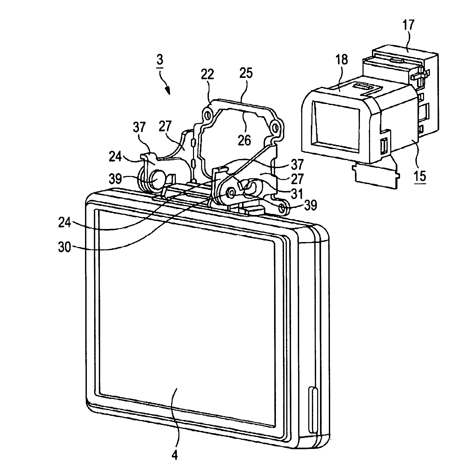
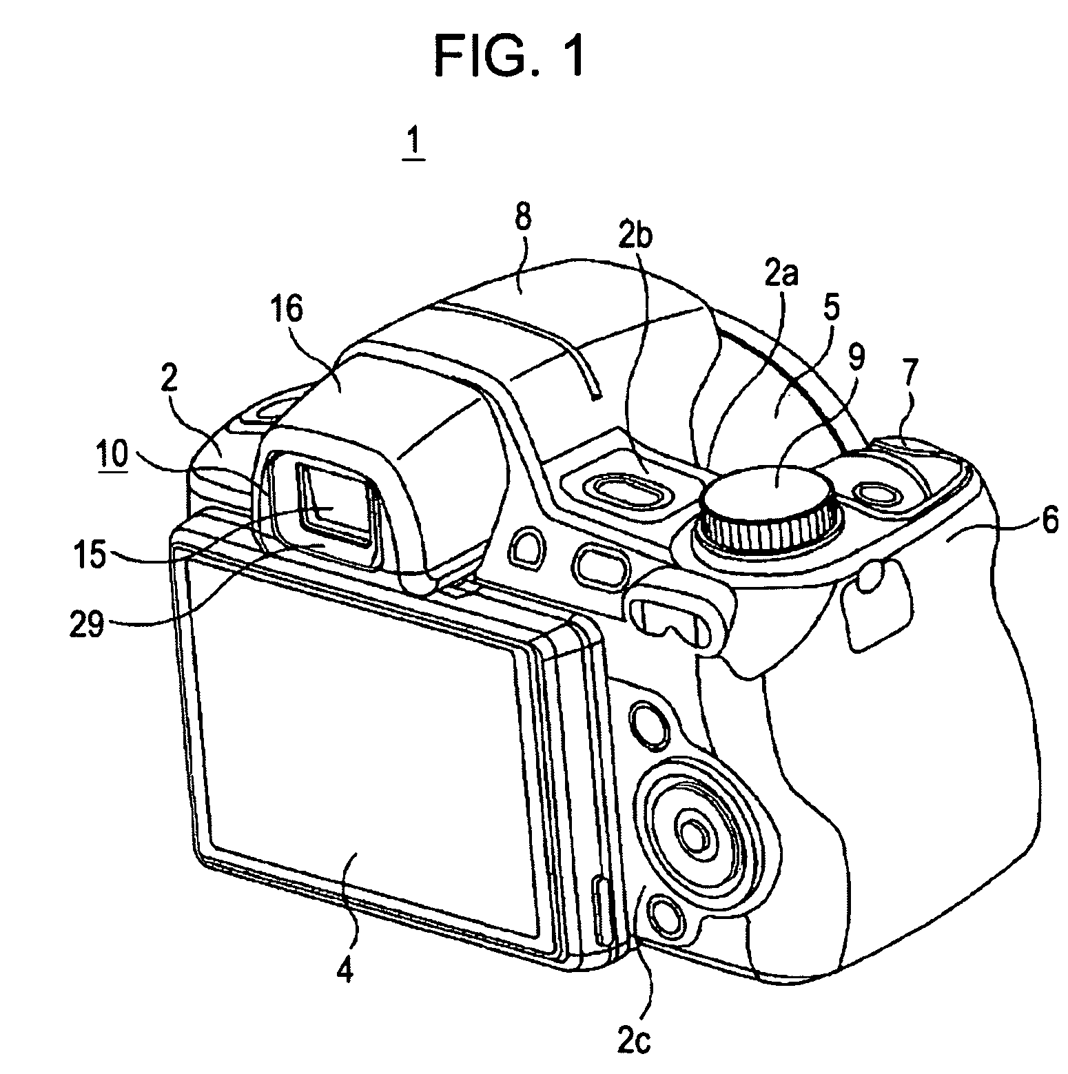
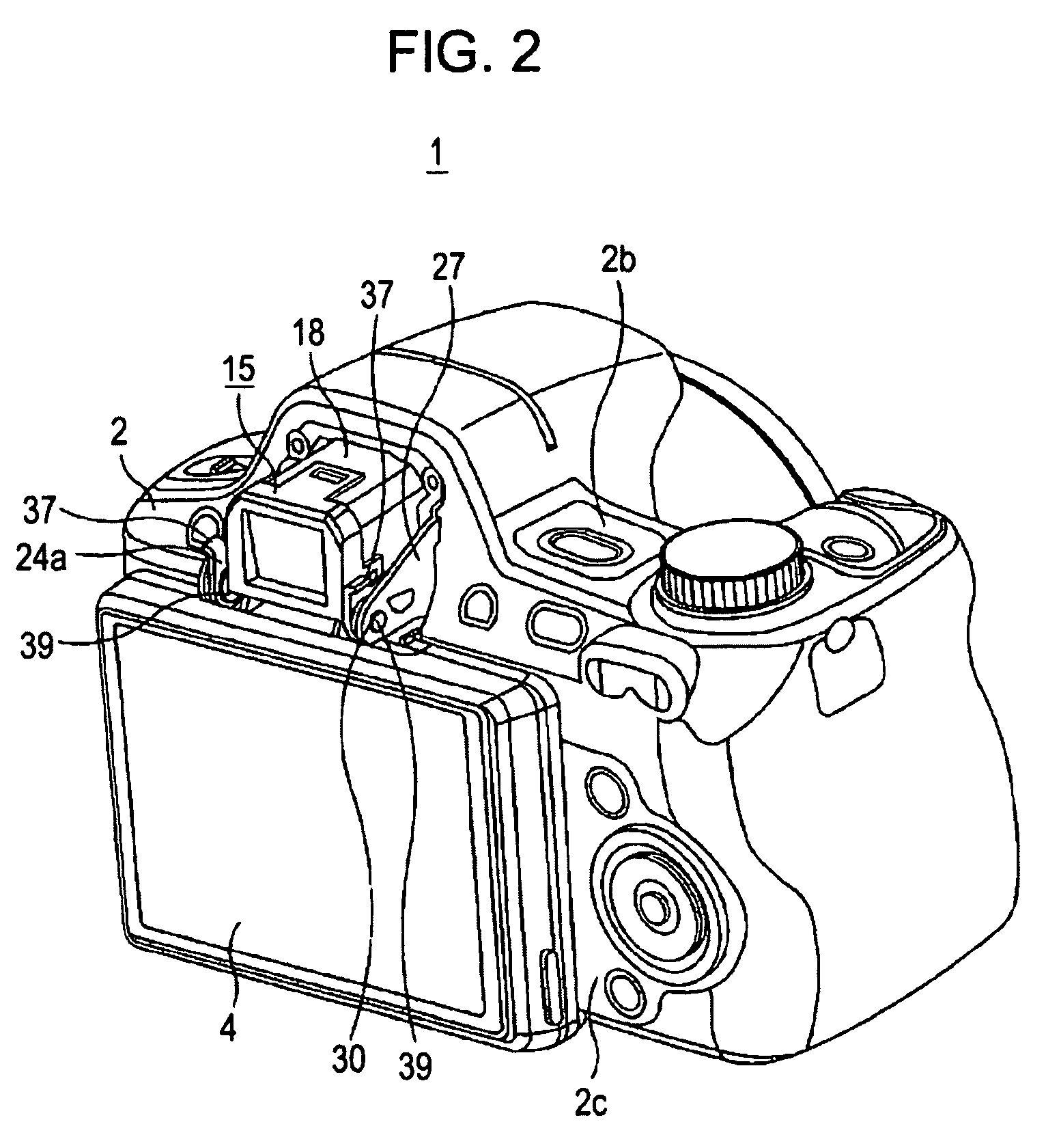
[0034]Hereinafter, an imaging apparatus according to an embodiment of the present invention is described in detail with reference to the drawings. FIG. 1 shows an imaging apparatus 1, which is a digital still camera or a film camera. The imaging apparatus 1 includes a camera body 2 and a liquid crystal monitor 4. The liquid crystal monitor 4 is supported by a hinge mechanism 3 such that the liquid crystal monitor 4 is rotatable relative to the camera body 2.

[0035]The camera body 2 is substantially rectangular in cross-section so that the user can easily hold the body with one hand. The camera body 2 has a lens barrel 5 containing an image-taking lens on a front surface 2a, and a grip 6 that bulges out. A user can stably hold the camera body 2 with the grip 6 bulging toward the front surface 2a. A shutter button 7 is provided on the grip 6 of the camera body 2 so that the user can readily click the shutter button 7 while holding the camera body 2. Such camera body 2 effectively reduc...


PUM


Abstract

An imaging apparatus includes an apparatus body, a monitor connected to the apparatus body, and a hinge mechanism including a support member. The supporting mechanism includes a mounting portion on a first end, the mounting portion being rotatably mounted on the apparatus body, and a supporting portion on a second end, the supporting portion supporting the monitor. The support member rotatably supports the monitor relative to the apparatus body. The support member of the hinge mechanism is disposed at substantially the same height as that of a viewfinder disposed on the apparatus body.

Description

CROSS REFERENCES TO RELATED APPLICATIONS[0001]The present invention contains subject matter related to Japanese Patent Application JP 2008-034979 filed in the Japanese Patent Office on Feb. 15, 2008, the entire contents of which are incorporated herein by reference.BACKGROUND OF THE INVENTION[0002]1. Field of the Invention[0003]The present invention relates to an imaging apparatus including a viewfinder and a monitor that displays an image captured by the apparatus body, and in particular, to an imaging apparatus having a monitor rotatably mounted on the apparatus body.[0004]2. Description of the Related Art[0005]An imaging apparatus such as a digital camera has a monitor of a liquid crystal display (LCD) panel or the like on the apparatus body. With the monitor, a user can check an image captured by the imaging apparatus body on the spot. The monitor is generally installed in the back surface of the apparatus body that faces the user when a user takes a picture. The user can take p...

Claims


Application Information

Patent Timeline
Patent Type & Authority Patents(United States)
IPC IPC(8): H04N5/222H04N5/225G03B13/02
CPCG03B13/00H04N5/2251H04N5/23293H04N23/531H04N23/63
Inventor KUSATSUGU, TAKASHITAKAHASHI, YUTAKAKUROYANAGI, KENICHI
Owner SONY CORP
Why Eureka
Try Eureka