Bone void filling tube and shear mechanism

a filling tube and bone void technology, applied in the field of bone void filling tube and shear mechanism, can solve the problems of simple wear, bone chips to tears,

Inactive Publication Date: 2012-05-15
ARTHREX
View PDF5 Cites 58 Cited by
  • Summary
  • Abstract
  • Description
  • Claims
  • Application Information

AI Technical Summary

Problems solved by technology

This damage can range from bone chips to tears to simple wear.

Method used


Image

  • Bone void filling tube and shear mechanism
  • Bone void filling tube and shear mechanism
  • Bone void filling tube and shear mechanism

Examples


Embodiment Construction

[0015]The examples provided below detail the preferred embodiments of the present invention. Other features, embodiments, and advantages of the invention beyond those discussed in the detailed description will be obvious to those skilled in the art. Those skilled in the art should appreciate that many changes may be made to the present invention without departing from the scope or spirit of the present invention.

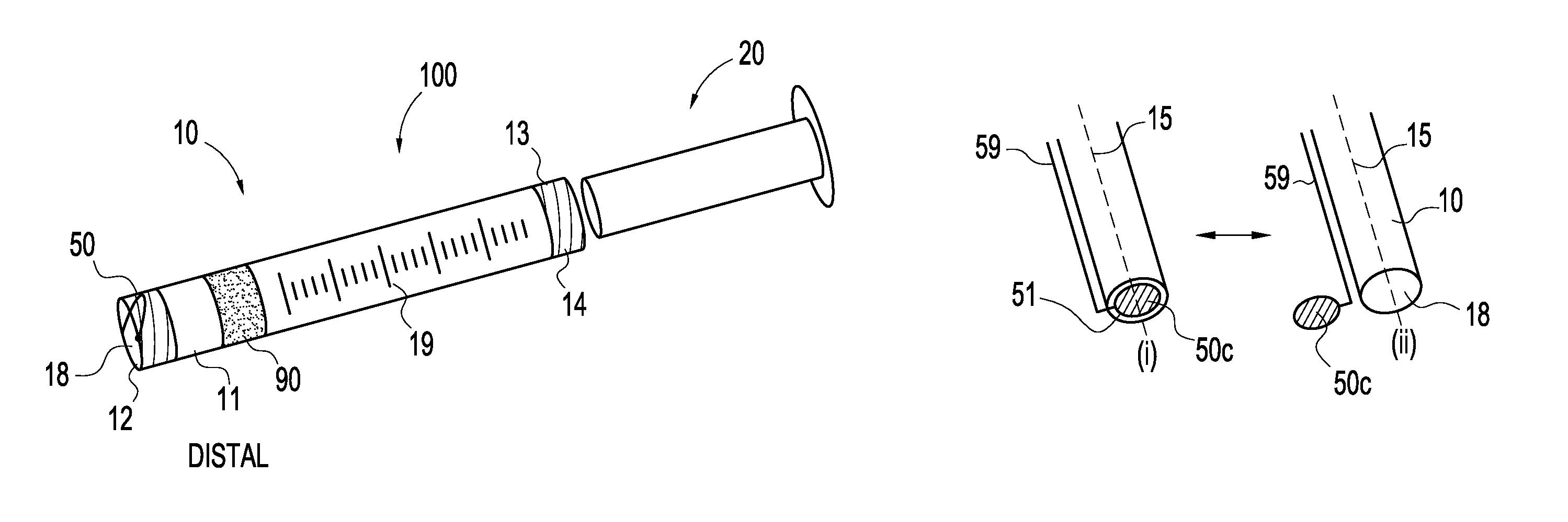
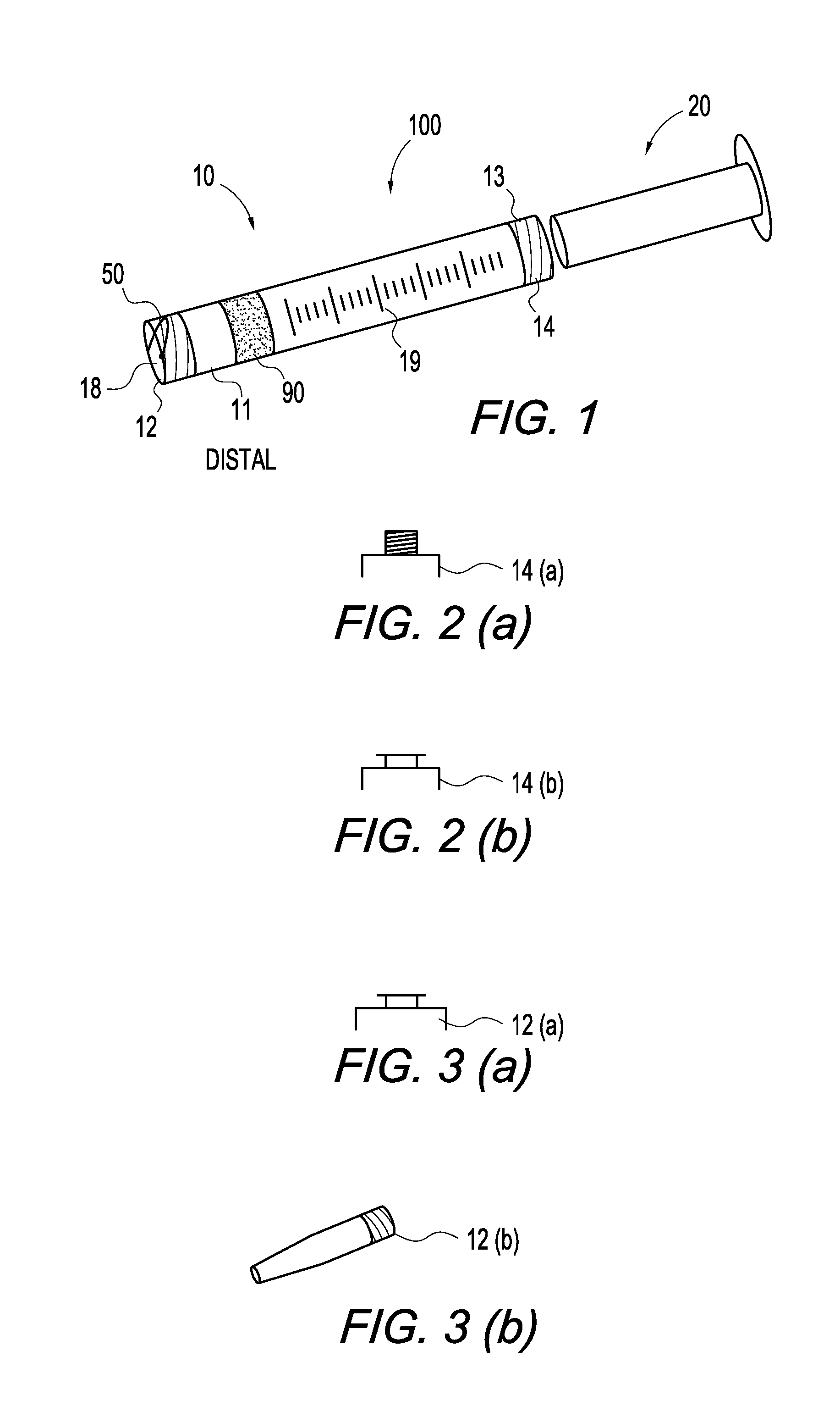
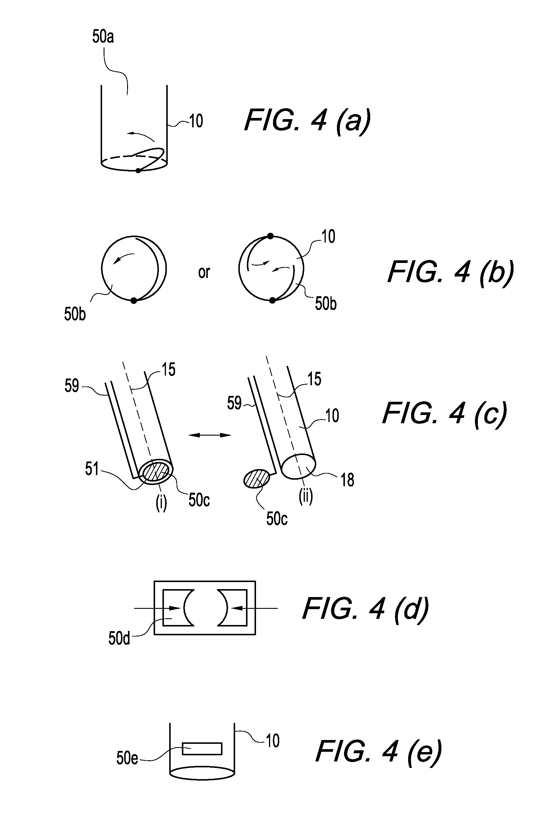
[0016]The present invention provides methods and apparatus for delivering a clotted biological component (such as blood, autologous conditioned plasma (ACP), platelet-rich plasma (PRP), bone marrow aspirate (BMA), demineralized bone matrix, anticoagulants and / or clotting agents, growth factors, or any combination of these materials) into a tissue void (for example, a bone void such as a bone tunnel, socket, opening or cavity), and then cutting the clotted biological component with a cutting or shearing mechanism at the tissue surface (for example, the bone surface).

[0017]In ...


PUM


Abstract

Apparatus and methods for delivering a clotted biological component (such as blood, autologous conditioned plasma (ACP), platelet-rich plasma (PRP), bone marrow aspirate (BMA), demineralized bone matrix, anticoagulants and / or clotting agents, or combination of these materials) into a tissue void (for example, a bone void such as a bone tunnel, socket, opening or cavity), and then cutting the clotted biological component with a cutting or shearing mechanism at the tissue surface. The apparatus is provided with a tube and a cutting or shearing mechanism (provided on or within the distal end of the tube) that is actuated to cut or break off the clot at the desired insertion length. The tube may then be placed over the next tissue void so that the obturator drives the next clot into the next tissue void until all tissue voids are filled. Upon insertion at the defect site, the biological component advances the healing of the damaged tissue and tissue growth.

Description

CROSS-REFERENCE TO RELATED APPLICATIONS[0001]This application claims the benefit of U.S. Provisional Application No. 61 / 229,159, filed Jul. 28, 2009, the entire disclosure of which is incorporated by reference herein.FIELD OF THE INVENTION[0002]The present invention relates to the delivery of a biological clot to a tissue void such as a bone void.BACKGROUND OF THE INVENTION[0003]Joint injuries typically involve damage to the bones and / or tendons that form the joint. This damage can range from bone chips to tears to simple wear. In the case of bone chips or wear, it is often necessary to repair the damage by replacing the missing bone material. This has been typically accomplished by attaching an implant over the defect that replicates the original bone structure. It is often necessary to also fill out the bone void formed in the bone structure (i.e., a transosseous tunnel or socket at the defect site, or an OATS harvesting site) with biological materials such as blood and / or growth ...

Claims


Application Information

Patent Timeline
Patent Type & Authority Patents(United States)
IPC IPC(8): A61M31/00A61M5/00A61M5/315
CPCA61M1/02A61M2202/0415A61M2202/0427A61M2202/10
Inventor SCHMIEDING, REINHOLDBENEDICT, ROBERT
Owner ARTHREX
Why Eureka
Try Eureka