Reflector panel of an LED street lamp

a technology of led street lamps and reflector panels, which is applied in the direction of fixed installations, lighting and heating devices, lighting support devices, etc., can solve the problems of reducing the evenness index, and achieve the effect of improving the uniformity and utilization rate of light in the str

Active Publication Date: 2012-07-17
ZHEJIANG JINGRI LIGHTING TECH
View PDF2 Cites 7 Cited by
  • Summary
  • Abstract
  • Description
  • Claims
  • Application Information

AI Technical Summary

Benefits of technology

[0008]As the preference, the multiple reflector cups are arranged in rectangular manner on the base plate, so the entire illumination zone of the LED street lamp is a rectangle that can match with the shape of the street and improve the utilization rate of the light.
[0032]3. In the present invention, a series of preferential measures are taken, such as the buckle is mounted at the back of the reflector cup, the reinforcing rib is mounted along the edge of the base hole, which ensure the stable and accurate position of the reflector cup and the reflecting efficiency of the reflector cup.

Problems solved by technology

The illumination zone of the LED street lamps with condensing lens currently used is a circular area, the two illumination zones formed by the two adjacent street lamps cannot join resulting in multiple dark areas in the street, which largely decrease the evenness index; whereas along the width direction of the street, two edges of the circular light area have many invalid illumination zones, which are wasteful.

Method used


Image

  • Reflector panel of an LED street lamp
  • Reflector panel of an LED street lamp
  • Reflector panel of an LED street lamp

Examples


embodiment 1

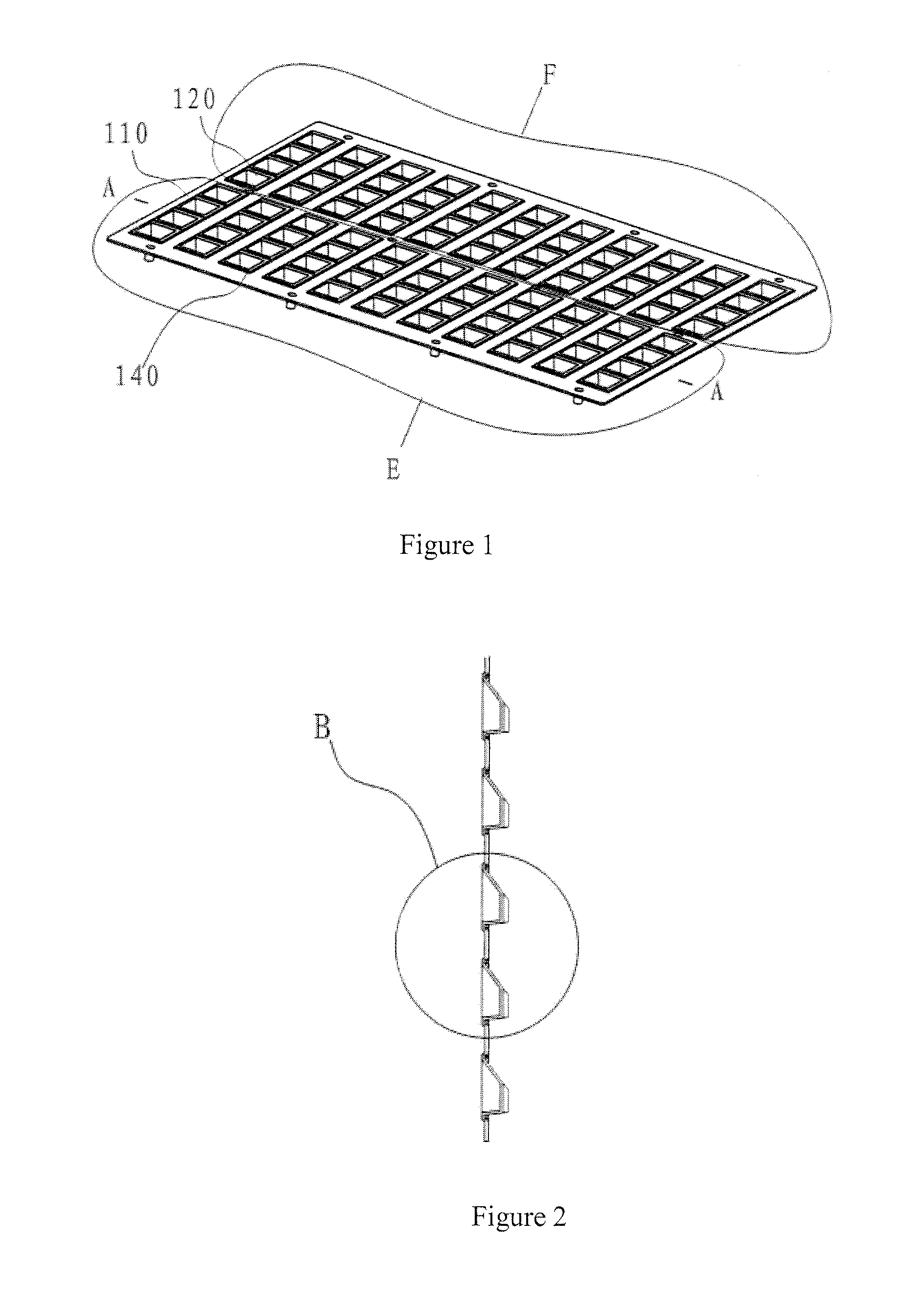
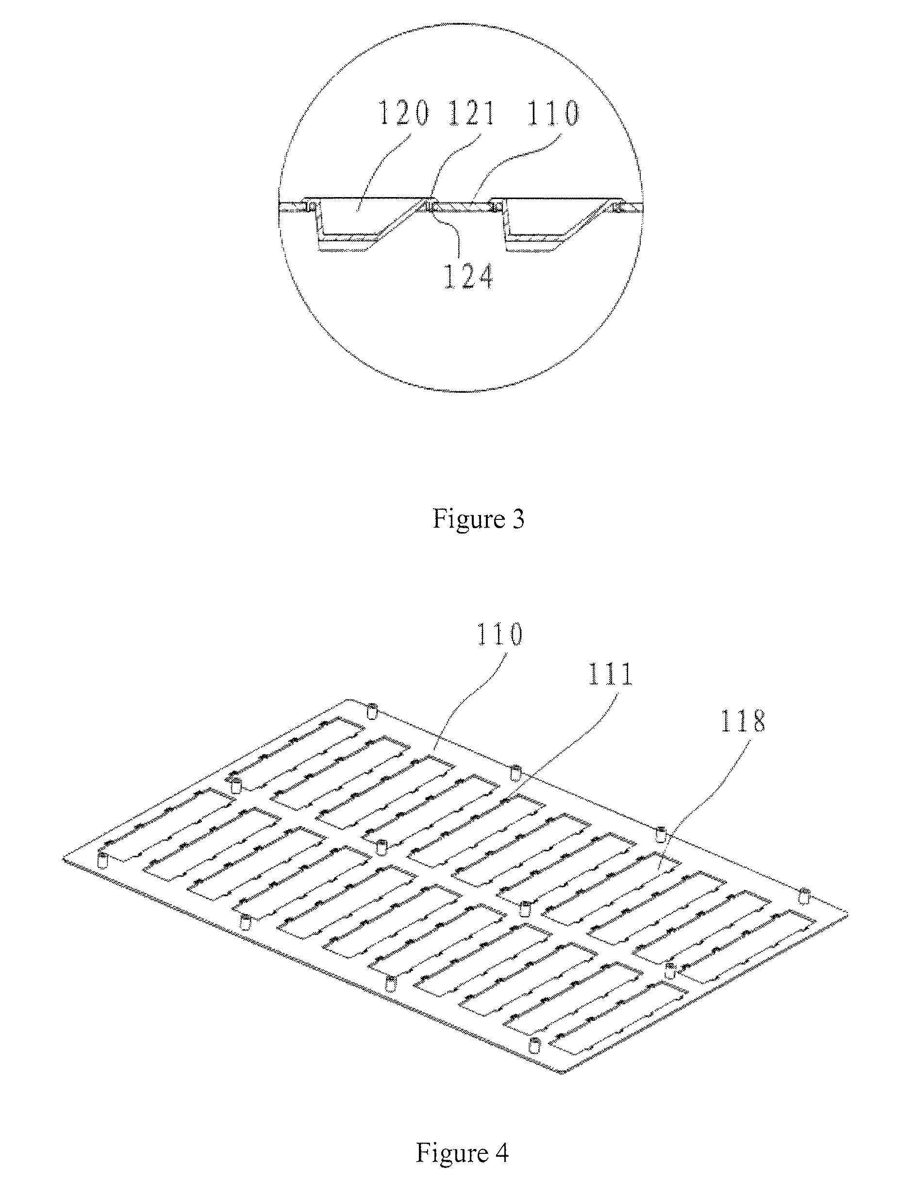
[0046] as shown in FIG. 1-7, a reflector cup of a LED street lamp, comprising base plate 110, the base plate 110 is divided into two parts that are distributed symmetrically. As shown in the figure, the left part E is introduced in detailed herein. In the left part E, there are 11 parallel base holes 118, and in each base hole 118 there are a reflector cup module group 140 with opening towards left direction, as shown in FIGS. 5, 6 and 7, the reflector cup module group 140 consists of 4 reflector cups 120 that are distributed side by side. The openings of the reflector cups 120 in the reflector cup module group 140 in left part E also is towards the left, each reflector cup 120 covers a light emitting diode, the light from the light emitting diode is emitted along the opening direction of the reflector cup after it is reflected by the reflecting face of the reflector cup. Correspondingly, the openings of all reflector cups in right part F points to right direction. Therefore, the li...

embodiment 2

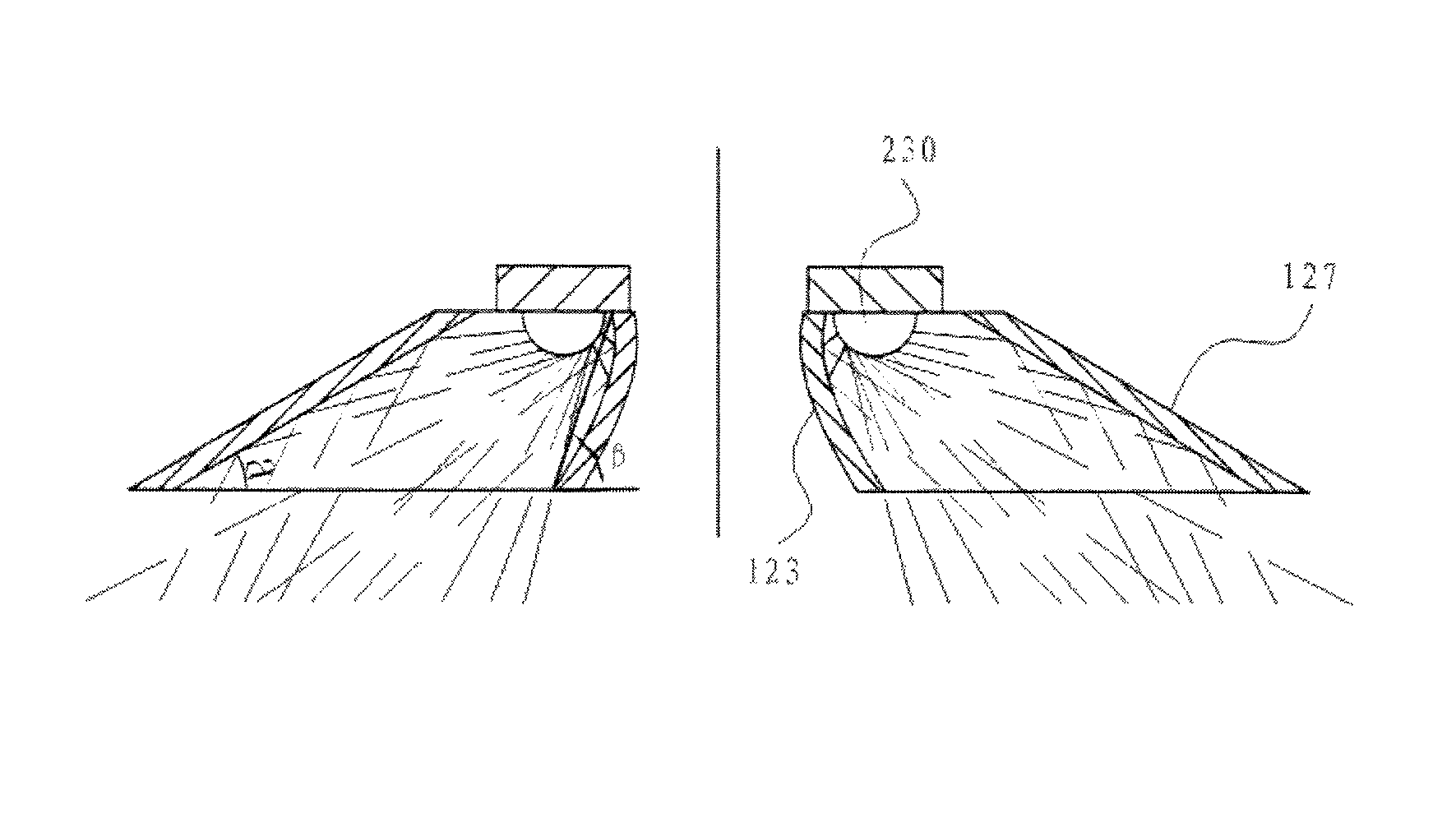
[0049] As shown in FIGS. 8˜13, a reflector panel of the LED street lamp, comprising two parts, each of which has 12 base holes. The base hole is for holding the reflector cup 120, and the opening direction of the reflector cups 120 in these two parts is different, the middle line between two parts is perpendicular to the street direction, the reflector cups 120 in the two parts reflect the light emitted from the light emitting diodes respectively towards the front and back directions along the street direction. FIG. 10 is a sectional view of the reflector cup 120 along the street direction, which shows the track of the reflected light along the street direction by the reflector cups, as shown in this the inner transverse face 123 and the outer transverse face 127 on the street, the said two faces control the length and evenness of the illumination band formed by the reflector cups along the street direction.

[0050]This figure also shows that these two faces can evenly distribute the ...


PUM


Abstract

The present invention relates to the technical field of LED street lamp, in particular to structure of a reflector panel of the LED lamp. A reflector panel comprises a base, the base has multiple reflector cups, which are divided into two groups according to the direction of their openings, all reflector cups in each group have the same direction of their openings, the directions of the openings of the reflector cups in two different groups are opposite. The reflector panel of the present invention can form the illumination band with even illuminance on the street and cause small light loss.

Description

TECHNICAL FIELD[0001]The present invention relates to a LED street lamp, in particular to a reflector panel thereof.BACKGROUND ART[0002]The high power LED (it means that the power of a single LED is not less than 1 W) lighting is a revolutionary technology that is currently recognized all over the world and can substitute the traditional lighting. The high power LED lamps can be used as the substitute of the currently used high power street lamps and flood lights.[0003]The LED used as the street lamp results in that the light emitted on the street is dark or the utilization rate of the light is lower since the LED particle's angle of illumination is small and the light's irradiating face is not even. The optimum illumination zone of the street lamp is a rectangular light area, the long edge of which coincides with the street direction and the short edge of which coincides with the street width. The illumination zone of the LED street lamps with condensing lens currently used is a ci...

Claims


Application Information

Patent Timeline
Patent Type & Authority Patents(United States)
IPC IPC(8): F21V21/00
CPCF21V7/0083F21V7/04F21V7/09F21V17/164F21W2131/103F21Y2101/02F21Y2105/001Y02B20/72F21Y2105/10F21Y2115/10F21S8/085
Inventor CHENG, SHIYOU
Owner ZHEJIANG JINGRI LIGHTING TECH
Why Eureka
Try Eureka