Receiving device for global positioning system and antenna structure thereof
a global positioning system and receiving device technology, applied in the direction of resonant antennas, elongated active element feeds, instruments, etc., can solve the problems of increasing manufacturing costs and achieving the effect of convenient carrying, reduced size and firm structur
- Summary
- Abstract
- Description
- Claims
- Application Information
AI Technical Summary
Benefits of technology
Problems solved by technology
Method used
Image

Examples
first embodiment
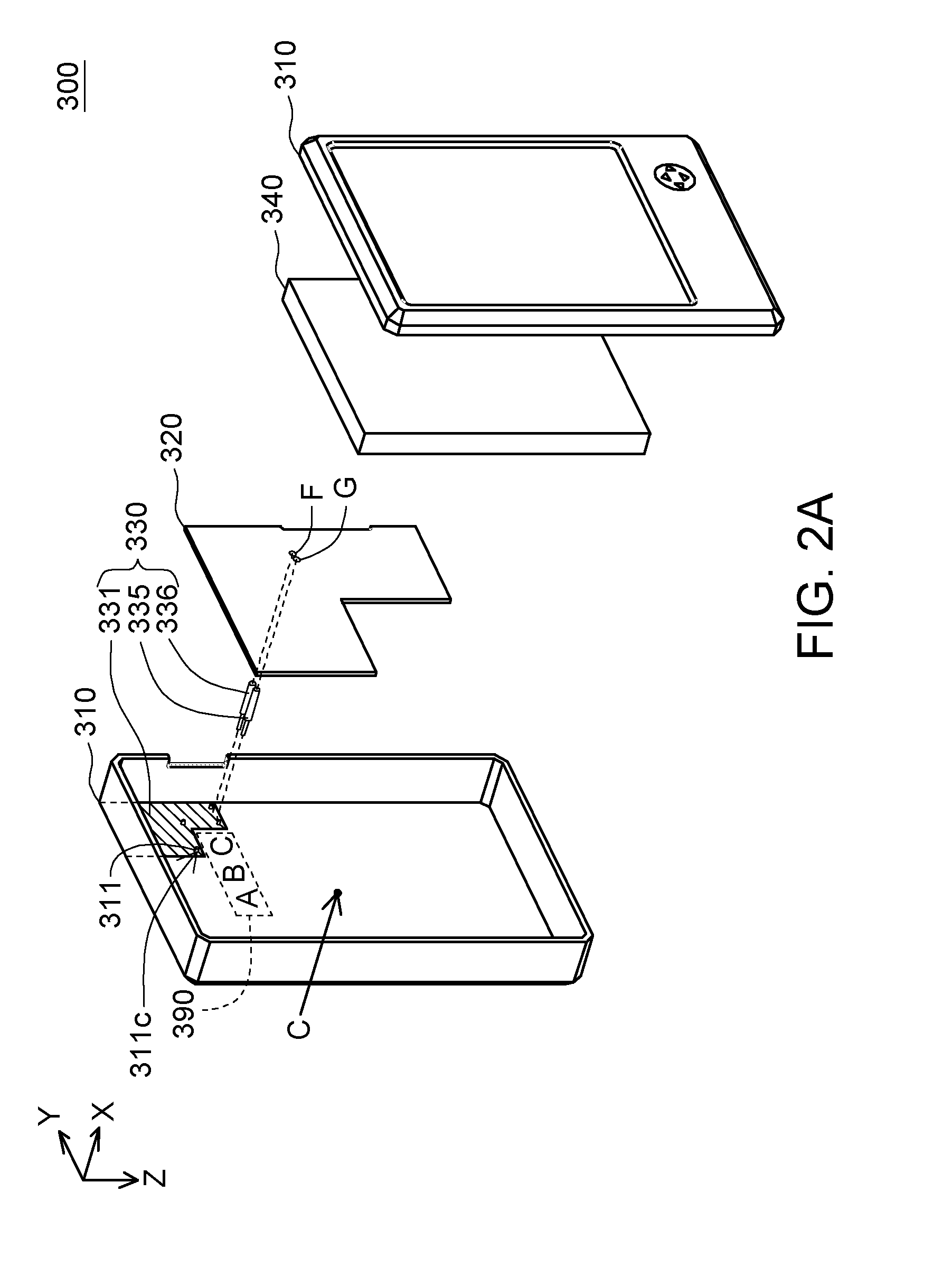
[0027]FIG. 2A is a schematically exploded view showing a receiving device 300 for a global positioning system according to a first embodiment of the invention. Referring to FIG. 2A, the receiving device 300 for the global positioning system includes a housing 310, a circuit board 320, an antenna structure 330 and a display 340. The circuit board 320 and the antenna structure 330 are disposed inside the housing 310. The display is exposed out of the housing 310 for displaying a data image. In this embodiment, the antenna structure 330 is a planar inverted F antenna (PIFA). The antenna structure 330 includes a metal plate 331, a first electric conducting element 335 and a second electric conducting element 336. The metal plate 331 is disposed on one side of the circuit board 320 for receiving a GPS signal transmitted from a satellite. The first electric conducting element 335 has one end coupled to the metal plate 331, and the other end coupled to a ground portion G of the circuit boa...
second embodiment
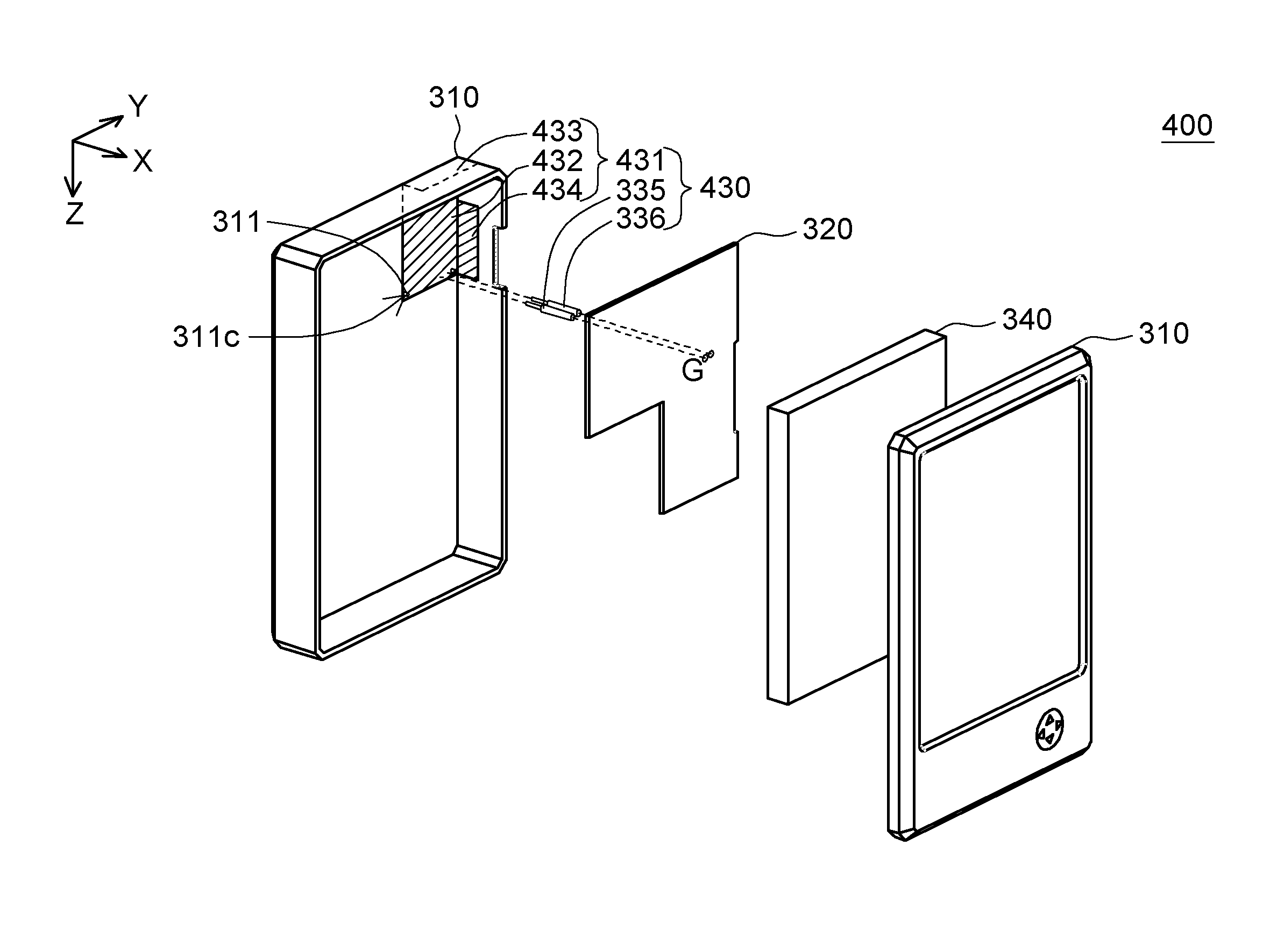
[0038]FIG. 4A is a schematically exploded view showing a receiving device 400 for a global positioning system according to a second embodiment of the invention. FIG. 4B is an illustration showing an antenna structure 430 of FIG. 4A. As shown in FIGS. 4A and 4B, the difference between the receiving device 400 according to this embodiment and the receiving device 300 according to the first embodiment resides in the antenna structure 430, and other elements similar to those of the first embodiment are indicated by the same symbols in FIGS. 2A so that detailed descriptions for other elements in this embodiment will be omitted.
[0039]As shown in FIG. 4A, the antenna structure 430 includes a metal plate 431, a first electric conducting element 335 and a second electric conducting element 336. The metal plate 431 includes a main body plate 432, a first extension plate 433 and a second extension plate 434. One end of the first electric conducting element 335 and one end of the second electri...
third embodiment
[0040]FIG. 5A is a schematically exploded view showing a receiving device 500 for a global positioning system according to a third embodiment of the invention. FIG. 5B is an illustration showing an antenna structure 530 of FIG. 5A. As shown in FIGS. 5A and 5B, the difference between the receiving device 500 according to this embodiment and the receiving device 300 according to the first embodiment resides in the antenna structure 530, and the other elements similar to those of the first embodiment are indicated by the same symbols in FIGS. 2A so that detailed descriptions for other elements in this embodiment thereof will be omitted.
[0041]Referring to FIG. 5A, the antenna structure 530 includes a metal plate 531, a first electric conducting element 535 and a second electric conducting element 536. The metal plate 531 has a rectangular structure and is supported on a supporting member 510 disposed on a housing 310. The supporting member 510 may be made of any material, which cannot i...
PUM
 Abstract
Description
Claims
Application Information
 - R&D
- Intellectual Property
- Life Sciences
- Materials
- Tech Scout
- Unparalleled Data Quality
- Higher Quality Content
- 60% Fewer Hallucinations
Browse by: Latest US Patents, China's latest patents, Technical Efficacy Thesaurus, Application Domain, Technology Topic, Popular Technical Reports.
© 2025 PatSnap. All rights reserved.Legal|Privacy policy|Modern Slavery Act Transparency Statement|Sitemap|About US| Contact US: help@patsnap.com