Graphite backscattered electron shield for use in an X-ray tube
What is AI technical title?
AI technical title is built by PatSnap AI team. It summarizes the technical point description of the patent document.
a backscattered electron shield and electron shield technology, applied in the field of x-ray tubes, can solve the problems of high voltage instability and potential tube failur
Active Publication Date: 2012-12-11
RAPISCAN SYST INC (US)
View PDF9 Cites 27 Cited by
Summary
Abstract
Description
Claims
Application Information
AI Technical Summary
This helps you quickly interpret patents by identifying the three key elements:
Problems solved by technology
Method used
Benefits of technology
Problems solved by technology
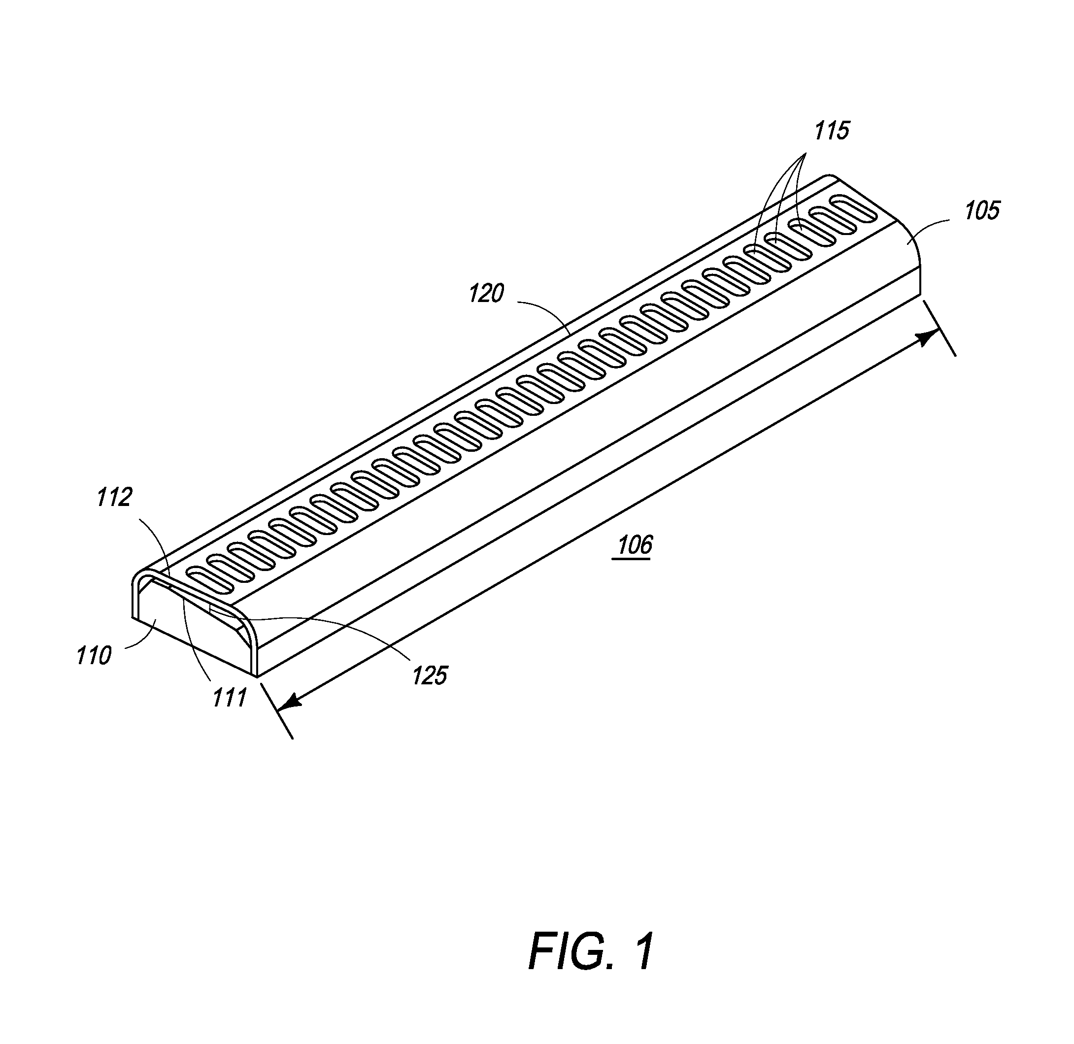
The consequence of this backscattering is that electrical charge can be deposited on surfaces within the tube which, if not dissipated, can result in high voltage instability and potential tube failure.
Method used
Image
Click on the blue label to locate the original text in one second.
Reading with bidirectional positioning of images and text.
Examples
Embodiment Construction
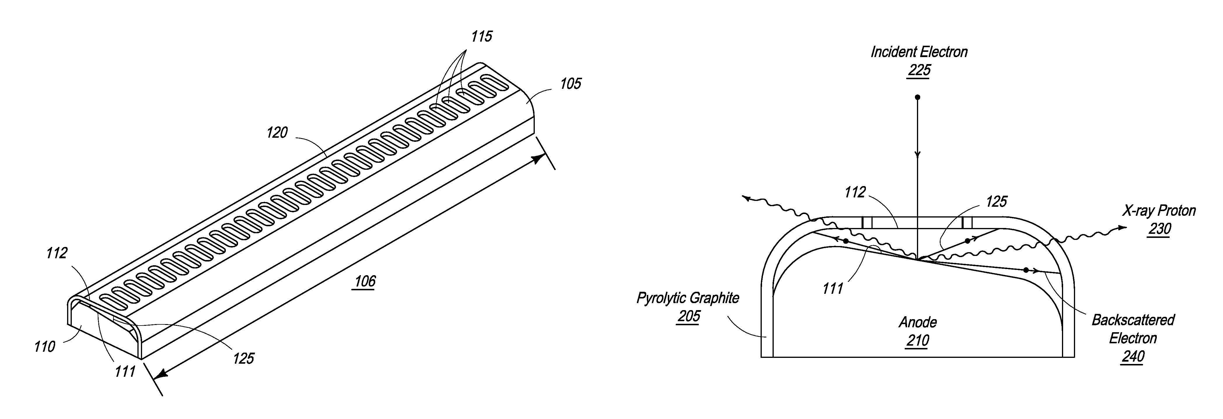
[0020]The present invention is directed towards an apparatus and method for preventing electrons, generated in an X-ray tube, from leaving an anode and entering the X-ray tube vacuum.
[0021]The present invention is also directed towards an apparatus and method for reducing the amount of backscattered electrons leaving the anode area that a) still allows free access of the incident electrons to the anode and b) does not impact the resultant X-ray flux.
[0022]In one embodiment, the present invention is directed towards a shield that can be attached to an anode while still allowing free access of incident electrons to the anode, wherein the shield is made of any material that will absorb or repel backscattered electrons while still permitting X-ray photons to pass through.
[0023]In one embodiment, the present invention is directed towards a pyrolitic graphite shield that can be attached to an anode while still allowing free access of incident electrons to the anode.
[0024]Thus, in one embo...
PUM
Abstract
The present invention is a shielded anode having an anode with a surface facing an electron beam and a shield configured to encompass the anode surface. The shield has at least one aperture and an internal surface facing the anode surface. The shield internal surface and anode surface are separated by a gap in the range of 1 mm to 10 mm. The shield of the present invention is fabricated from a material, such as graphite, that is substantially transmissive to X-ray photons.
Description
CROSS-REFERENCE TO RELATED APPLICATIONS[0001]The present application relies on U.S. Patent Provisional Application Ser. No. 61 / 183,591 filed on Jun. 3, 2009, for priority.[0002]The present application is also a continuation-in-part of U.S. patent application Ser. No. 12 / 485,897, filed on Jun. 16, 2009 now abandoned, which is a continuation of U.S. patent application Ser. No. 10 / 554,656, filed on Oct. 25, 2005, and now issued U.S. Pat. No. 7,564,939, which is a 371 national stage application of PCT / GB04 / 01729, filed on Apr. 23, 2004 and which, in turn, relies on Great Britain Application No. 0309387.9, filed on Apr. 25, 2003, for priority.[0003]The present application is also a continuation-in-part of U.S. patent application Ser. No. 12 / 371,853, filed on Feb. 16, 2009 now U.S. Pat. No. 7,903,789, which is a continuation of U.S. patent application Ser. No. 10 / 554,975, filed on Oct. 25, 2005, and now issued U.S. Pat. No. 7,512,215, which is a 371 national stage application of PCT / GB200...
Claims
Application Information
Patent Timeline
Application Date:The date an application was filed.
Publication Date:The date a patent or application was officially published.
First Publication Date:The earliest publication date of a patent with the same application number.
Issue Date:Publication date of the patent grant document.
PCT Entry Date:The Entry date of PCT National Phase.
Estimated Expiry Date:The statutory expiry date of a patent right according to the Patent Law, and it is the longest term of protection that the patent right can achieve without the termination of the patent right due to other reasons(Term extension factor has been taken into account ).
Invalid Date:Actual expiry date is based on effective date or publication date of legal transaction data of invalid patent.

