Photographic device

a technology of a photographic device and a lens module, which is applied in the field of photographic devices, can solve the problems of easy damage to the lens module under water drops may cover the inner surface of the optical spherical mask, and the lens module is even damaged accordingly, so as to prevent improve the service life of the photographic device. , the effect of preventing the decrease of the photograph quality

Active Publication Date: 2013-02-26
VIVOTEK INC
View PDF5 Cites 9 Cited by
  • Summary
  • Abstract
  • Description
  • Claims
  • Application Information

AI Technical Summary

Benefits of technology

[0008]In view of the above problems, the disclosure provides a photographic device to prevent the problem of the lens in the optical spherical mask of the conventional photographic device being easier to be damaged due to the collision by a foreign object or man-made impact. Also, the disclosure can prevent the problem of the low photograph quality and the decreasing service life of a conventional photographic device due to the influence on the photographic device by the moisture and dust.
[0010]As the upper casing of the photographic device is made of high impact-resistant material, for example, an aluminum alloy, the upper casing is firm and not easy to be destroyed in nature. In addition, the transparent mask is located under the through hole of the upper casing. The size of the through hole is according to the range of the view angle of the lens module, and the transparent mask does not protrude from the outer surface of the upper casing. Accordingly, the upper casing can prevent the transparent mask from being impacted, and, therefore, broken by a force, thereby protecting the lens in the transparent mask. In addition, the photographic device may has a water-proof member, for example, a water-proof rubber, so that the connection slits between the upper casing and the transparent mask, the upper casing and the lower cover, and the upper casing and the signal line set can be sealed. Then the photographic device can be ensured that the space enclosed by the upper cover component and the lower cover is a sealed space in which the lens module and the circuit board are located. In this way, such sealed space can provide a water-proof effect and a dust-proof effect to the photographic device to prevent the decrease of the photograph quality due to the accumulation of moisture or dust on an inner surface of the transparent mask. Also, the sealed space prevents the damage caused by the direct contact of the moisture and the dust with a circuit unit in the photographic device, thereby improving the service life of the photographic device.

Problems solved by technology

However, the optical spherical mask of the conventional photographic device protrudes from the upper casing, and, therefore, is easier to be damaged from collision, man-made impact or hit with a tool.
The lens module under the optical spherical mask is even damaged accordingly.
In addition, as the photographic device has no water-proof structure and dust-proof structure, water drops may cover the inner surface of the optical spherical mask due to the existence of the moisture in the fixed photographic device.
Also, a layer of dust may cover the inner surface of the optical spherical mask due to the entering of the dust particles into the photographic device.
Therefore, such water drops and the layer of dust may lower the quality of the photographed picture.
Moreover, even short circuit may be caused by the attachment of the water drops and the dust onto a circuit unit in the photographic device, causing the decrease of the service life of the photographic device.
As the upper casing of the photographic device is made of high impact-resistant material, for example, an aluminum alloy, the upper casing is firm and not easy to be destroyed in nature.

Method used


Image

  • Photographic device
  • Photographic device
  • Photographic device

Examples


Embodiment Construction

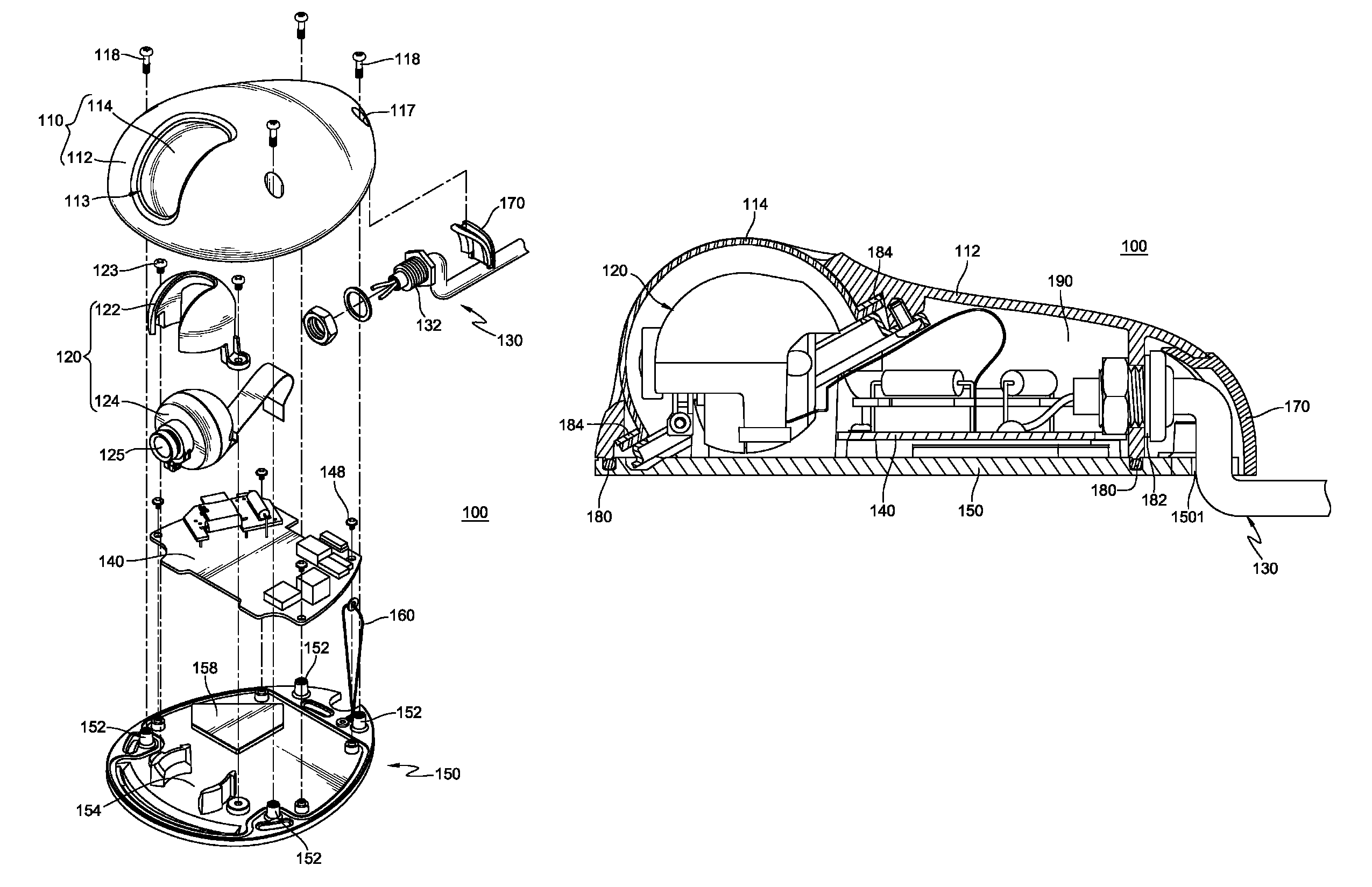
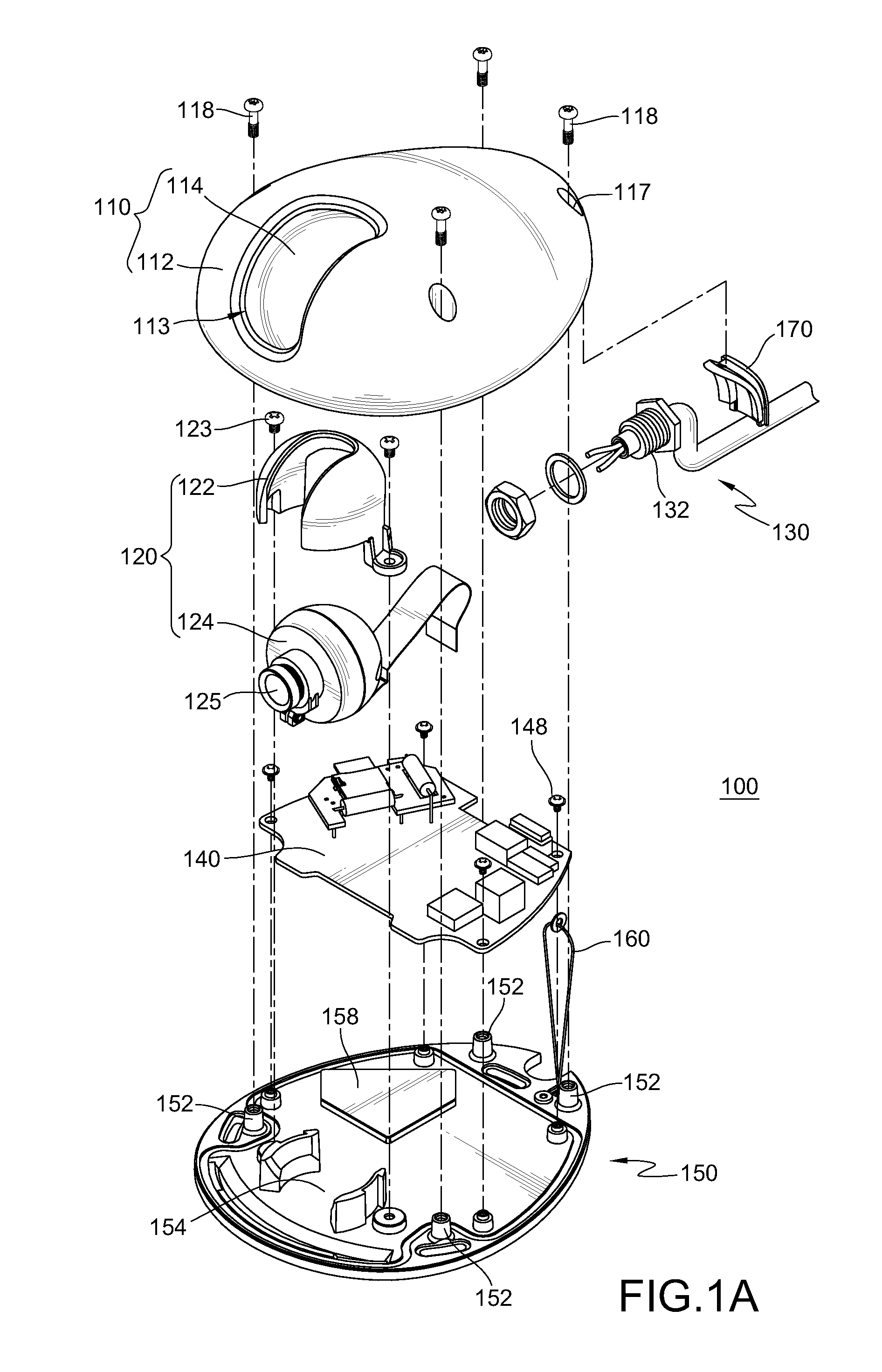
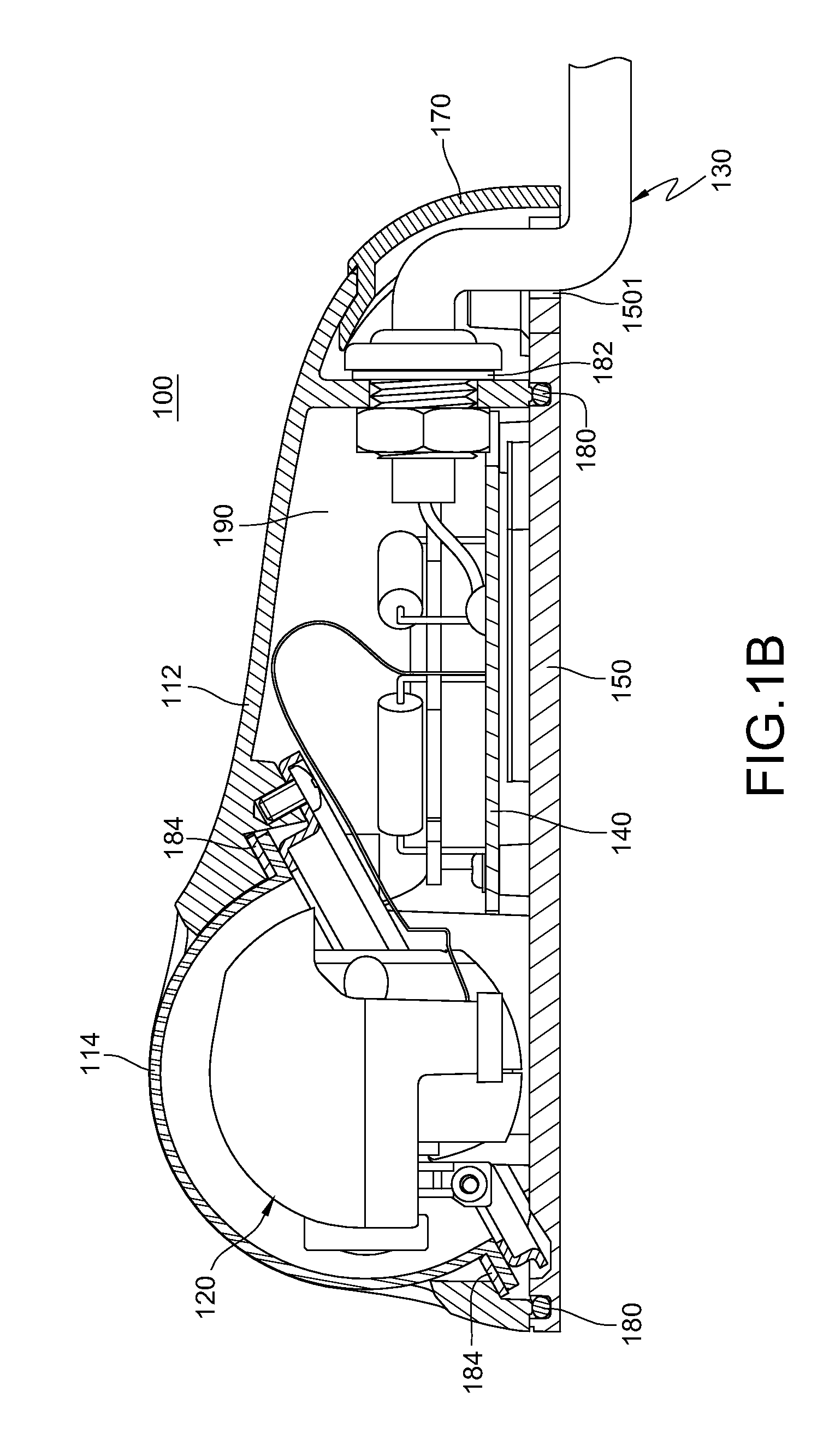
[0018]FIG. 1A is an exploded view of a photographic device according to an embodiment, FIG. 1B is a sectional view of the photographic device as shown in FIG. 1A, and FIG. 1C is a sectional view of the photographic device in FIG. 1A without a line cover 170.

[0019]As shown in FIGS. 1A to 1C, a photographic device 100 comprises an upper cover component 110, a lens module 120, a signal line set 130, a circuit board 140, and a lower cover 150. The upper cover component 110 comprises an upper casing 112 and a transparent mask 114. The upper casing 112 has a through hole 113 which is an elongated breach. The transparent mask 114 is fastened in the upper casing 112 and disposed under the through hole 113. The through hole 113 exposes the transparent mask 114 which does not protrude from the upper casing 112. The lens module 120 is in the transparent mask 114, and the view angle of the lens module 120 can be adjusted according to the breach range of the through hole 113.

[0020]A conventional...


PUM


Abstract

A photographic device includes an upper cover component, a lens module, a signal line set, a circuit board, and a lower cover. The upper cover component comprises an upper casing having a through hole and a transparent mask. The transparent mask is fastened under the through hole and exposed by it and does not protrude from an outer surface of the upper casing. The lens module has a photographic lens facing the mask. The signal line set has a fixing end fastened to one end of the upper casing. The circuit board is electrically connected to the lens module and the signal line set. The lower cover and the upper casing are joined and enclose the lens module and the circuit board. As the transparent mask does not protrude from the outer surface of the upper casing, cracks of the transparent mask caused by a foreign object can be prevented.

Description

CROSS-REFERENCE TO RELATED APPLICATIONS[0001]This non-provisional application claims priority under 35 U.S.C. §119(a) on Patent Application No(s). 099213004 filed in Taiwan, R.O.C. on Jul. 7, 2010, the entire contents of which are hereby incorporated by reference.BACKGROUND[0002]1. Technical Field[0003]The present disclosure relates to a photographic device, and more particularly, to a photographic device for preventing damages.[0004]2. Related Art[0005]A conventional photographic device is mounted at a particular position on an indoor ceiling, an indoor wall, or an outdoor wall, for photographing an indoor or outdoor scene at a particular view angle. The conventional photographic device has a lens module, a circuit board, a signal line set, an upper casing, and a lower casing. The upper casing has an optical spherical mask generally made of plastic and protruding from an outer surface of the upper casing, and the lens module is accommodated in the optical spherical mask. The circui...

Claims


Application Information

Patent Timeline
Patent Type & Authority Patents(United States)
IPC IPC(8): G03B17/00
CPCG03B17/02G03B17/08G08B13/19619
Inventor CHENG, SZU-HSINGHSU, CHIH-HUI
Owner VIVOTEK INC
Why Eureka
Try Eureka