Charged particle cancer therapy patient positioning method and apparatus
What is AI technical title?
AI technical title is built by Patsnap AI team. It summarizes the technical point description of the patent document.
a cancer therapy and charge particle technology, applied in the field of solid tumor treatment, can solve the problems of reduced ability to repair damaged dna, confined place danger, and increased risk of cancer patients being attacked by dna
Active Publication Date: 2014-04-01
BALAKIN ANDREY VLADIMIROVICH +1
View PDF365 Cites 21 Cited by
Summary
Abstract
Description
Claims
Application Information
AI Technical Summary
This helps you quickly interpret patents by identifying the three key elements:
Problems solved by technology
Method used
Benefits of technology
Problems solved by technology
Benign tumors cause problems because of their spread, as they press and displace normal tissues.
Benign tumors are dangerous in confined places such as the skull.
These particles damage the DNA of cells, ultimately causing their death.
Cancerous cells, because of their high rate of division and their reduced ability to repair damaged DNA, are particularly vulnerable to attacks on their DNA.
Method used
Image
Click on the blue label to locate the original text in one second.
Reading with bidirectional positioning of images and text.
Examples
example iii
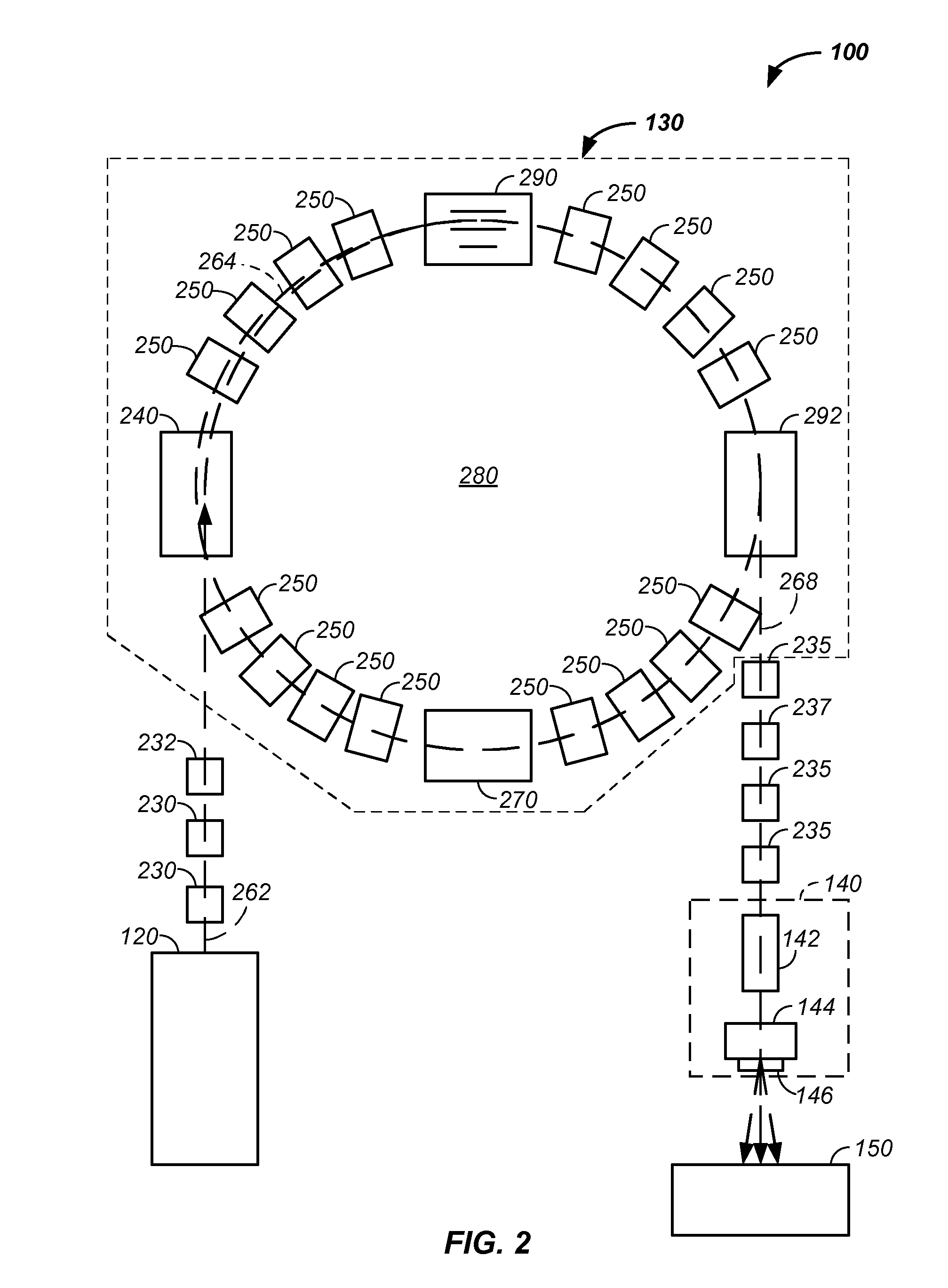
[0165]Referring again to FIG. 9, an example of a winding coil 930 that covers two turning magnets 510, 520 is provided. Optionally, a first winding coil 940 covers one magnets or a second winding coil 920 covers a plurality of magnets 510, 520. As described, supra, this system reduces space between turning section allowing more magnetic field to be applied per radian of turn. A first correction coil 910 is illustrated that is used to correct the magnetic field for the first turning magnet 510. A second correction coil 920 is illustrated that is used to correct the magnetic field for a winding coil 930 about two turning magnets. Individual correction coils for each turning magnet are preferred and individual correction coils yield the most precise and / or accurate magnetic field in each turning section. Particularly, the individual correction coil 910 is used to compensate for imperfections in the individual magnet of a given turning section. Hence, with a series of magnetic field sen...
PUM
Abstract
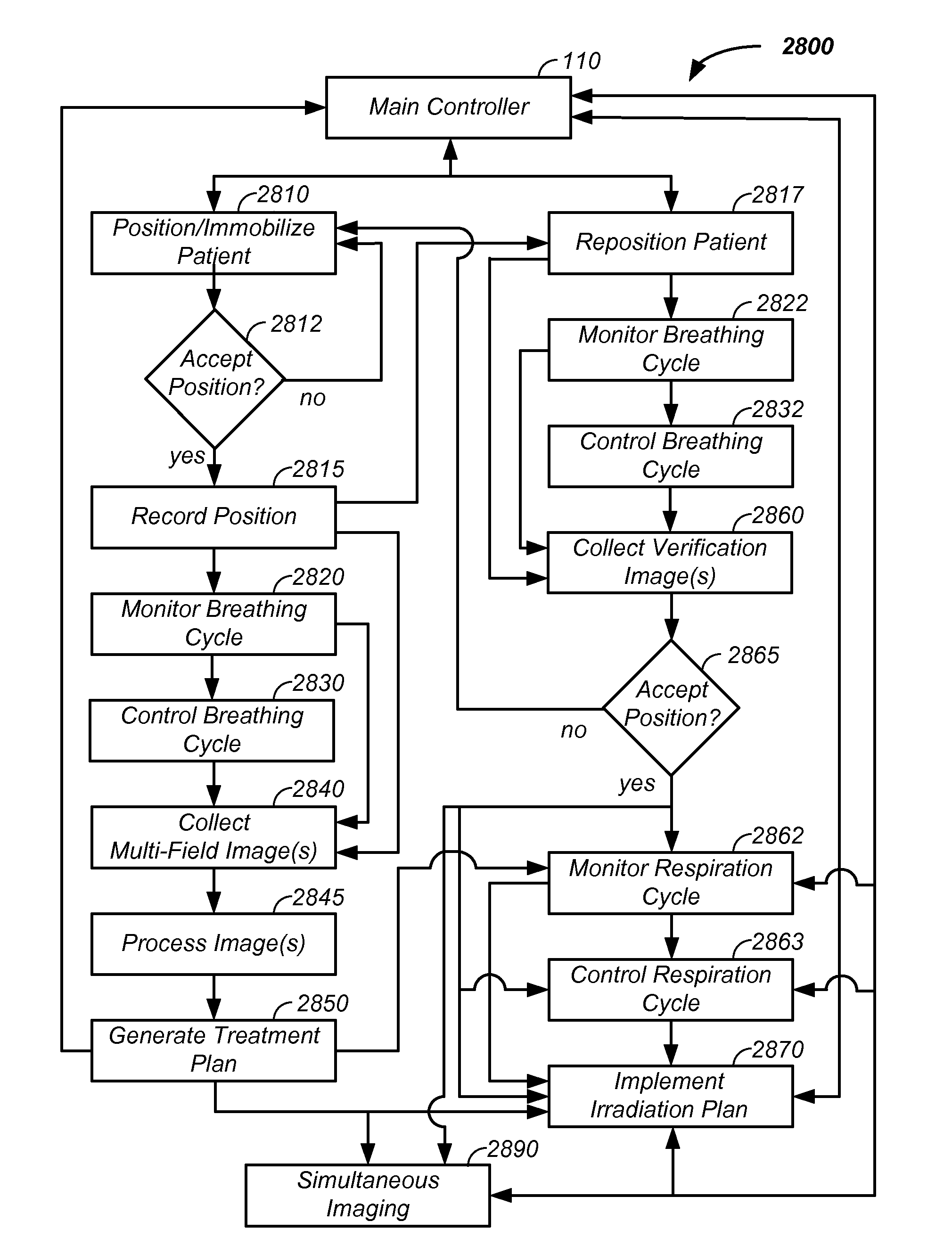
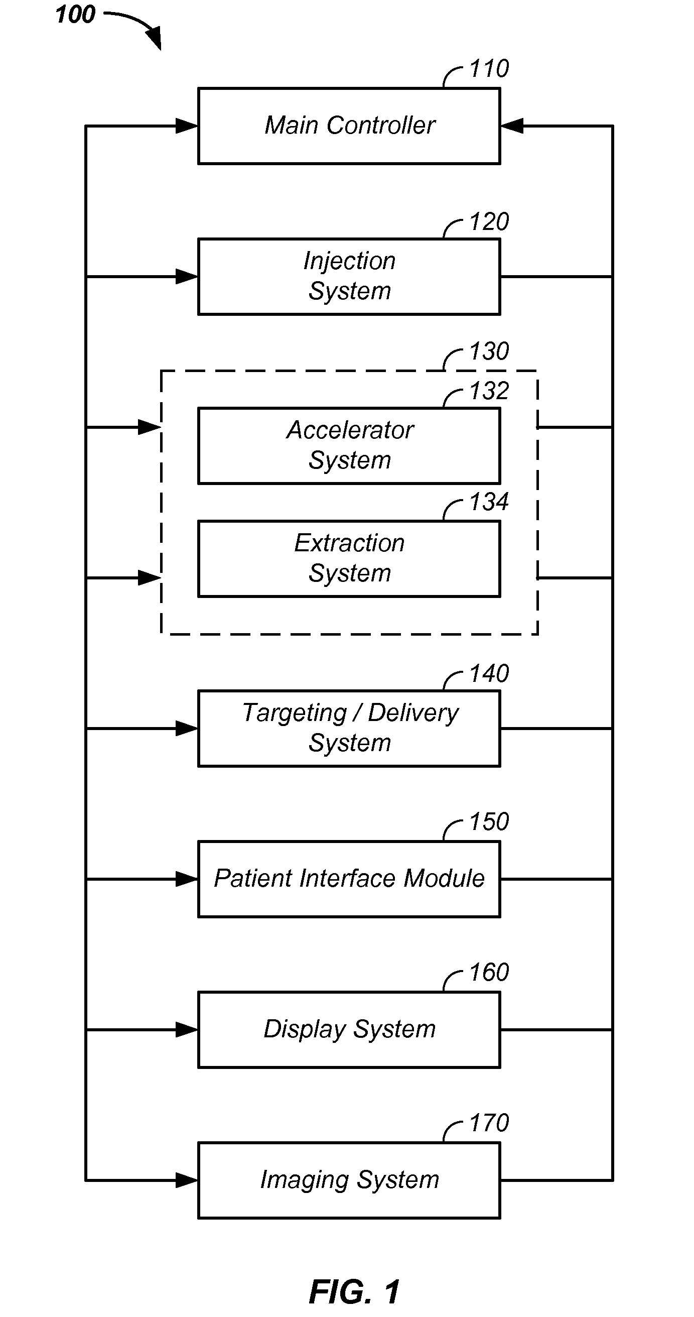
The invention comprises a patient positioning and / or repositioning system, such as a laying, semi-vertical, or seated patient positioning, alignment, and / or control method and apparatus used in conjunction with multi-axis charged particle radiation therapy. Patient positioning constraints optionally include one or more of: a seat support, a back support, a head support, an arm support, a knee support, and a foot support. One or more of the positioning constraints are preferably movable and / or under computer control for rapid positioning, repositioning, and / or immobilization of the patient. The system optionally uses an X-ray beam that lies in substantially the same path as a proton beam path of a particle beam cancer therapy system. The generated image is usable for: fine tuning body alignment relative to the proton beam path, to control the charged particle beam path to accurately and precisely target the tumor, and / or in system verification and validation.
Application Information
Patent Timeline
Application Date:The date an application was filed.
Publication Date:The date a patent or application was officially published.
First Publication Date:The earliest publication date of a patent with the same application number.
Issue Date:Publication date of the patent grant document.
PCT Entry Date:The Entry date of PCT National Phase.
Estimated Expiry Date:The statutory expiry date of a patent right according to the Patent Law, and it is the longest term of protection that the patent right can achieve without the termination of the patent right due to other reasons(Term extension factor has been taken into account ).
Invalid Date:Actual expiry date is based on effective date or publication date of legal transaction data of invalid patent.

