Methods and apparatus for a staple

a technology of method and apparatus, applied in the field of memory materials, can solve the problems of reducing the quality of fixation and limited the application of step staples, and achieve the effect of increasing the distance between the legs and expanding the bridge width

Active Publication Date: 2014-05-13
FOX WILLIAM CASEY
View PDF50 Cites 87 Cited by
  • Summary
  • Abstract
  • Description
  • Claims
  • Application Information

AI Technical Summary

Benefits of technology

[0009]In a second embodiment, the second member moves upward to extend a bridge width, thereby delivering a distraction force across the bridge and any legs disposed on the bridge. The upward movement further creates an offset force that may be utilized to reposition bones to anatomically correct positions relative to each other. Accordingly, it is possible to distract a first bone from a second bone, and reposition bones that have been dislodged bones.
[0010]It is therefore an object of the present invention to change shape to provide compression through a staple with a back section having two levels that change position relative to one another so as to decrease or increase the distance between the legs of the staple and simultaneously offset the two bone fragments or bring the two bone fragments into alignment.

Problems solved by technology

Though this staple has legs that deflect inwards during heating its stepped back does not change shape due to the undesired consequence of this shape change causing lifting of the back of the staple from the surface of the bone.
This lifting would, in the application of the high tibial osteotomy, reduce the quality of fixation because the legs would partially pull out of bone and the back of the staple would be prominent and visible under the skin.
These concerns have limited the applications of step staples to adapting to anatomical contours and taught against implants that change the shape of their back in all planes except the plane of the surface of the bone.

Method used


Image

  • Methods and apparatus for a staple
  • Methods and apparatus for a staple
  • Methods and apparatus for a staple

Examples


first embodiment

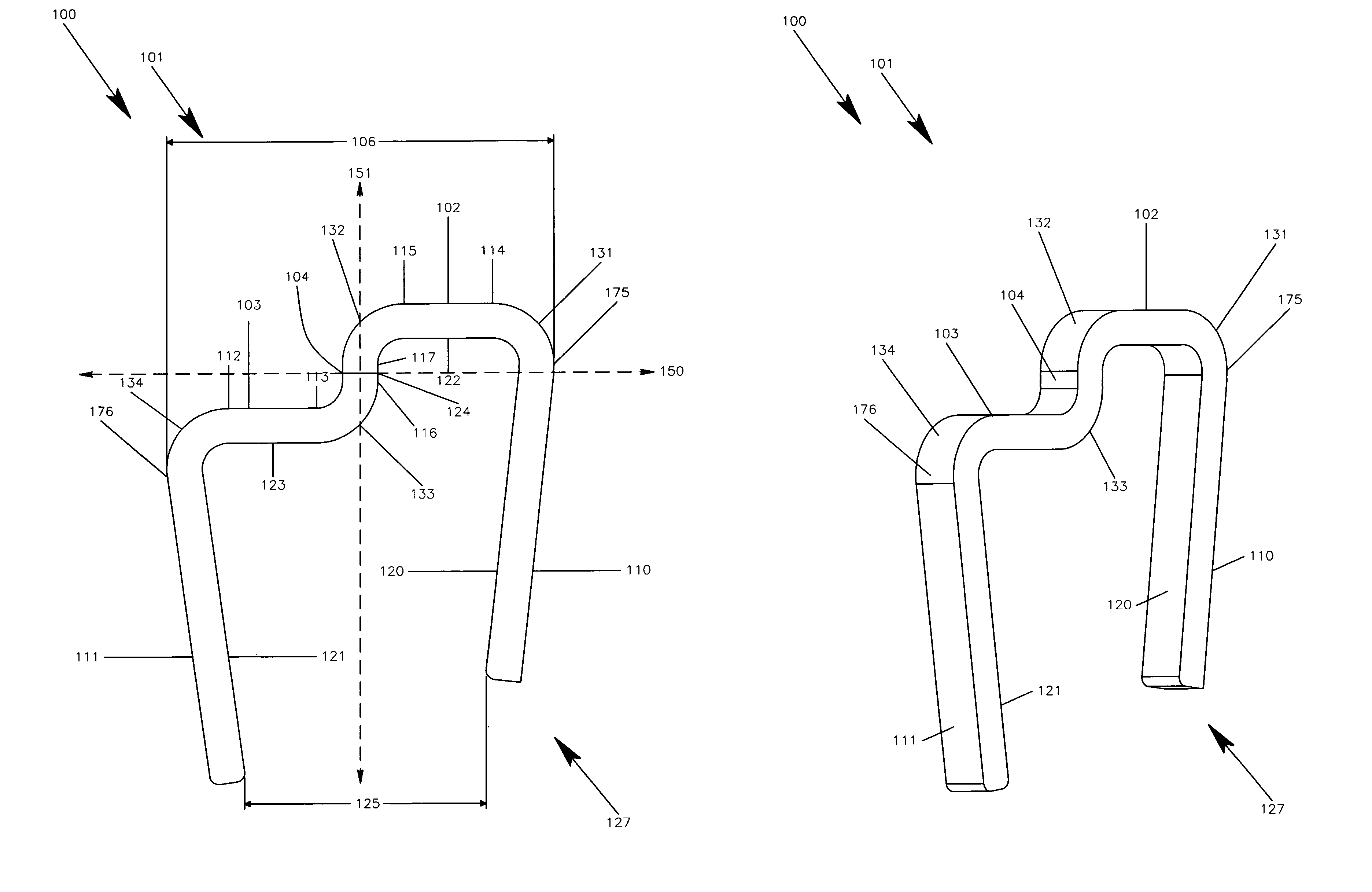
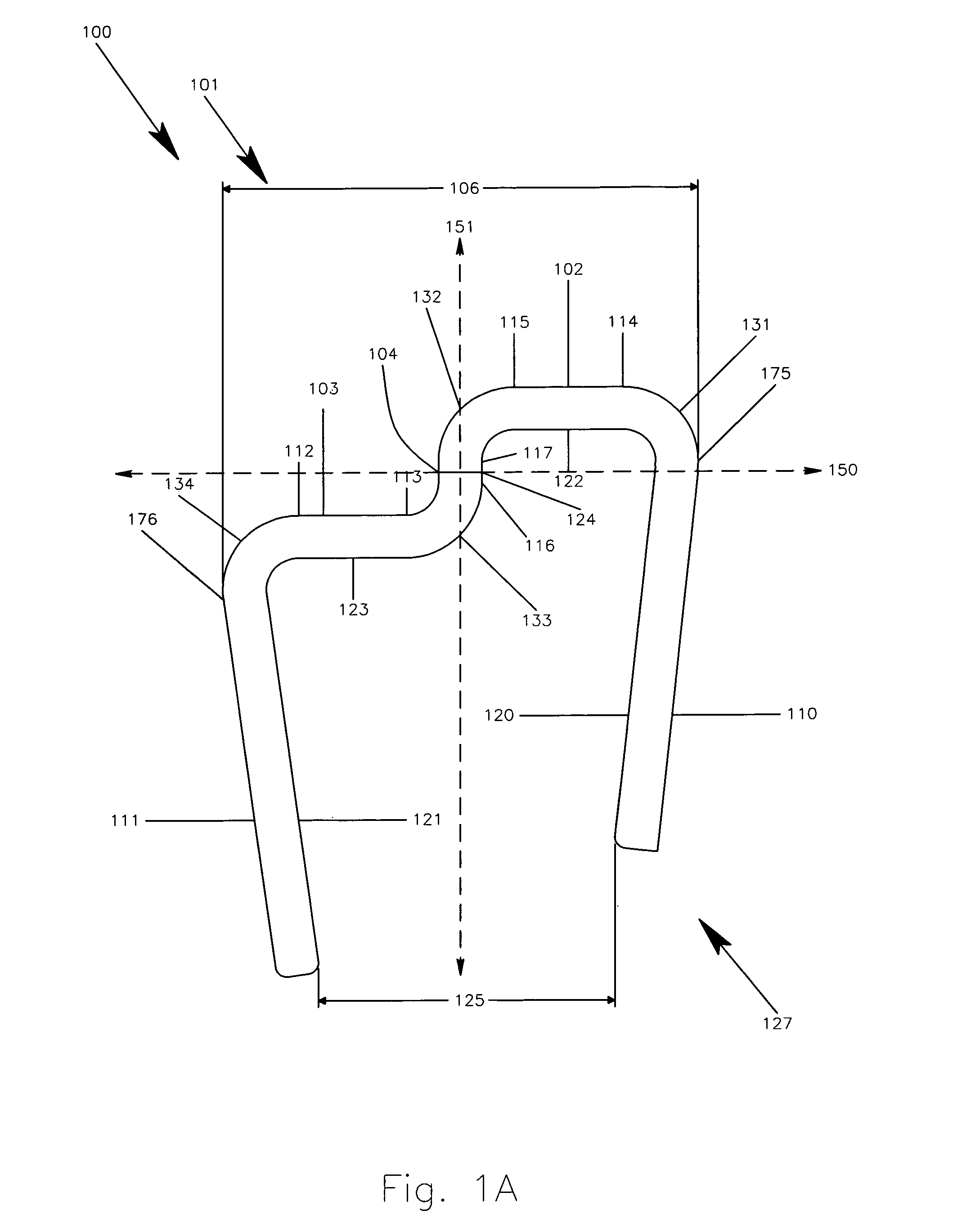
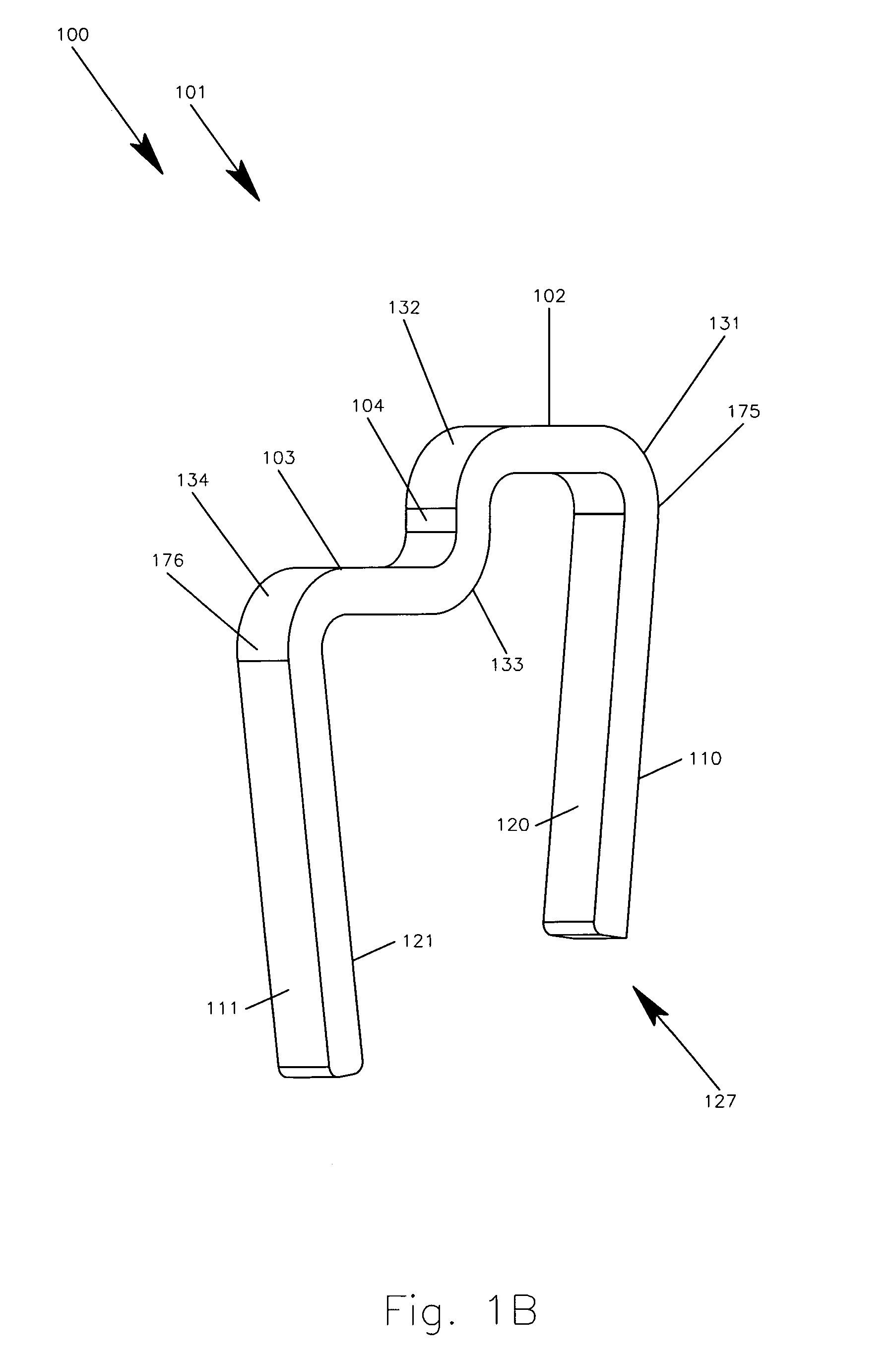
[0046]In this first embodiment, compressive forces are created between the first engagement surface 120 and the second engagement surface 121, thereby restraining the staple 100 in an installed position. Compressive forces are further created between the fifth engagement surface 124 and the first engagement surface 120, thereby aiding in the translation and rotation of the second leg 111 and the transition member 104. The rotation in the area of the second bend 132 forces the transition member 104 and the second member 103 downward and toward the first leg 110, thereby creating an offset force, whereby the second member 103 retains an attached bone at an elevation lower than the first member 102. The resultant forces 170 applied by the first leg 110 includes a horizontal component 172 that lies substantially parallel to the bridge 101 for clamping force, and a component 171 that lies substantially perpendicular to the bridge 101, thereby providing an increased retention force.

[0047]...

second embodiment

[0054]The staple 200 includes a first leg 210, a second leg, 211, and a bridge 201, which, in the first shape 227, has a bridge width 206, and in the second shape 228, has a bridge width 207. The bridge 201 has a first end 275 and a second end 276 includes a first member 202, a second member 203, and a transition member 204. In this example, the first member 202 and the second member 203 are planar, however, one of ordinary skill in the art will recognize that the shape of members 202 and 203 may be of any form, including, arcs, angles, and the like. In this second embodiment, the first leg 210 is connected to a first end 214 of the first member 202, and a second end 215 of the first member 202 is connected to a first end 217 of the transition member 204. The second leg 211 is connected to a first end 212 of the second member 203, and a second end 213 of the second member 203 is connected to a second end 216 of the transition member 204. The staple 200 further includes a first bend ...


PUM


Abstract

A staple constructed from shape memory material provides the ability to move from a first shape to any point up to and including a second shape. The staple includes a bridge having a first member and a second member, and allows the second member of the bridge to change elevation with respect to the first member, thereby creating compressive forces, offset forces, or distraction forces. Upon the application of energy, the second member moves upward or downward to deliver forces, dependent upon a desired effect. The staple further includes first and second legs for attaching to first and second bones. The offsetting forces may be utilized to offset the second bone relative to the first bone, or to align offset bones. The bridge may include a transition member or plurality of transition members in communication with the first and second members, whereby the transition member moves about the first member.

Description

BACKGROUND OF THE INVENTION[0001]1. Field of the Invention[0002]The present invention relates to shape memory materials, and, more particularly, but not by way of limitation, to methods and an apparatus for utilizing a shape memory staple as an aid in operations including osteologic synthesis.[0003]2. Description of the Related Art[0004]Wire and staple fixation of bone have been used clinically for over 50 years. Cerclage techniques have commonly been used to encircle bone with wire to secure it to an adjacent bony segment. Variants of this technique initially involved taking a cerclage wire and bending it into a U-shape and inserting it into bone to provide intrabony fixation. As time progressed specialized staple with two of four legs were developed. These staple implants were fabricated from materials such as stainless steel and chromium-cobalt alloys and impacted into bone or placed so that the legs of the staple were inserted in drill holes thus minimizing surgery induced fract...

Claims


Application Information

Patent Timeline
Patent Type & Authority Patents(United States)
IPC IPC(8): A61F2/30
CPCA61B17/0642A61B2017/00867
Inventor FOX, WILLIAM, CASEY
Owner FOX WILLIAM CASEY
Why Eureka
Try Eureka