Electronic circuit storage case and manufacturing method thereof

a technology for electronic circuits and storage cases, applied in the direction of electrical apparatus casings/cabinets/drawers, coupling device connections, instruments, etc., can solve the problems of art techniques failing to achieve the intended purpose of ventilating holes, and the structure to release a pressure directly to the exterior from the case portion is contrary to the waterproof structure, etc., to achieve the effect of easy and highly reliable manner

Active Publication Date: 2014-11-04
MITSUBISHI ELECTRIC CORP
View PDF3 Cites 1 Cited by
  • Summary
  • Abstract
  • Description
  • Claims
  • Application Information

AI Technical Summary

Benefits of technology

[0013]The invention was devised to solve the problems as discussed above and has an object to provide an electronic circuit storage case provided with a ventilating hole that lessens an internal pressure change in a resin case occurring with an ambient temperature change in a relatively easy and highly reliable manner.
[0016]The electronic circuit storage case configured as above is provided with the ventilating hole continuing from the interior of the case portion to the exterior of the connector portion in a solid portion of the housing. The interior opening hole and the communication hole are bent in an L shape and provided to the primary resin mold part forming the housing. The exterior opening hole is provided to the secondary resin mold part of the housing enclosing the primary resin mold part and forming the connector portion and the case portion so as to communicate with one end of the L-shaped communication hole substantially perpendicularly. Accordingly, a ventilating hole having two turns and allowing the case portion and the connector portion to communicate can be readily provided in a reliable manner merely by molding and an internal pressure change in the resin case can be lessened. It thus becomes possible to obtain an electronic circuit storage case provided with a highly reliable ventilating hole.
[0017]According to the manufacturing method of the electronic circuit storage case configured as above, the primary resin mold part having the interior opening hole and the communication hole bent in an L shape is molded in the primary resin molding step of forming the housing. The entire housing including the connector portion and the case portion is formed in the secondary resin molding step together with the exterior opening hole connected to one end of the L-shaped communication hole substantially perpendicularly by holding the primary resin mold part at a predetermined position in dies and filling a cavity therein with resin. Accordingly, the same advantage as above can be obtained.

Problems solved by technology

In this instance, because a water-proof case portion has a sealed structure, assuming that there is no pressure escape, stress concentrates on a thin portion, a joint or the like of a case member and may possibly cause damage.
It should be noted, however, that a structure to release a pressure directly to the exterior from the case portion is contrary to the waterproof structure.
In addition, because various electronic control units used in the engine room of the internal combustion engine are disposed in a narrow space, a layout thereof is limited and so is an insertion direction of a connector.
However, the methods of closing one of the opening holes respectively opening in three directions by melting the resin in the vicinity of the opening hole as in the related art techniques described in Patent Document 1 and Patent Document 2 described above have problems as follows.
That is, the ventilating hole may be filled with excessively melted resin running therein from the opening hole and the resin may further pass through the opening hole and run into the ventilating hole.
Hence, there is a problem that the related art techniques may fail to achieve the intended purpose of the ventilating hole.

Method used


Image

  • Electronic circuit storage case and manufacturing method thereof
  • Electronic circuit storage case and manufacturing method thereof
  • Electronic circuit storage case and manufacturing method thereof

Examples


first embodiment

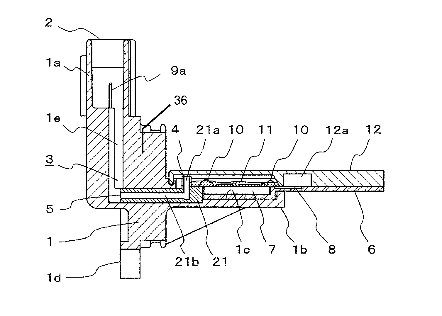
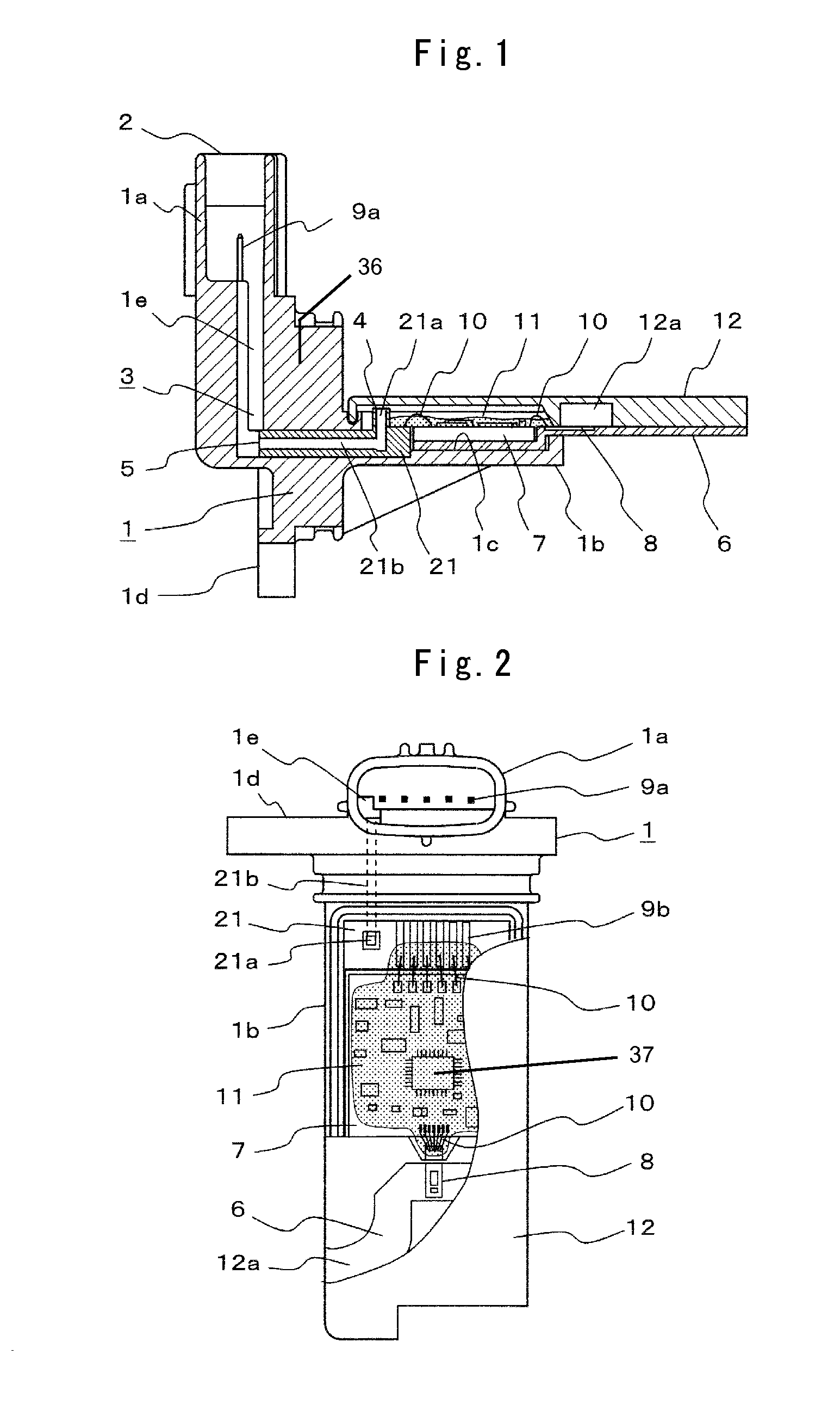
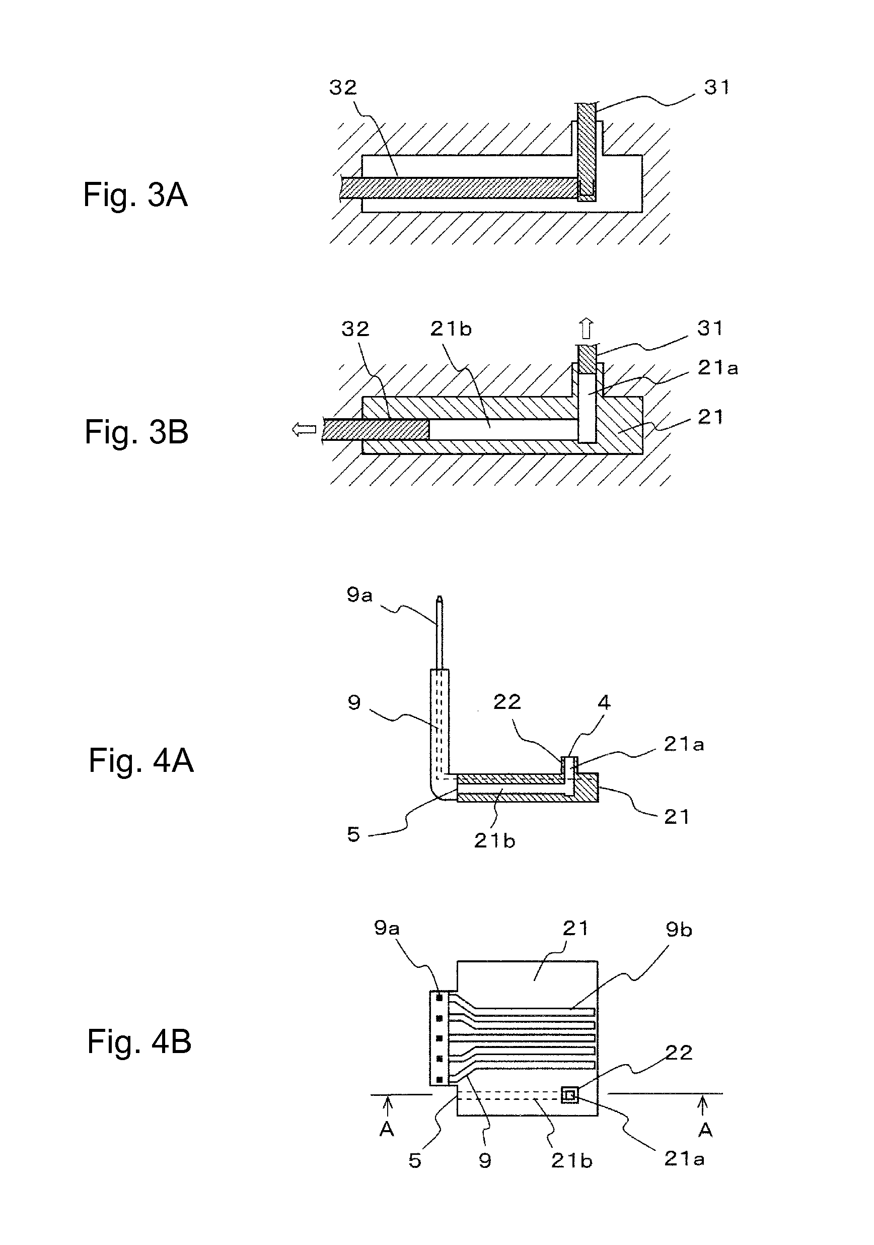
[0033]FIG. 1 is a sectional side view of a flow measuring device according to a first embodiment of the invention. FIG. 2 is a front view of the flow measuring device of FIG. 1 when viewed from a connector opening portion side. FIGS. 3A and 3B are views used to describe a molding step of a primary resin mold part as a component forming a housing of FIG. 1. FIGS. 4A and 4B are views showing the primary resin mold part formed according to FIGS. 3A and 3B. FIG. 5 is a cross section showing placement of dies during secondary resin molding to manufacture the housing of FIG. 1. FIG. 6 is a cross section of a major portion of FIG. 5. FIGS. 7A and 7B are cross sections taken on the arrow B-B of FIG. 5 and used to describe a secondary resin molding step of a connector portion. FIG. 8 is a sectional side view showing the overall housing after the secondary resin molding.

[0034]Firstly, an overall configuration of the flow measuring device will be described using FIG. 1 and FIG. 2.

[0035]A housi...

second embodiment

[0073]FIG. 9 is a front view of a major portion in a flow measuring device according to a second embodiment of the invention. The second embodiment is basically of the same configuration as that of the first embodiment shown in FIG. 1 and FIG. 2. FIG. 9 shows a portion corresponding to the portion shown in FIG. 2 but it shows the interior made visible by removing the cover 12. That is, FIG. 9 is a front view after the plate 6 on which is mounted the electronic circuit board 7 is attached to the housing 1. A description of the same portions as those in FIG. 1 and FIG. 2 is omitted and a difference will be chiefly described herein.

[0074]As with the first embodiment above, the primary resin mold part 21 of the housing 1 is provided with the interior opening hole 21a and the opening wall 22 is provided to the opening portion thereof. Also, the moisture-proof protective gel 11 is applied on the connection portion of the interior connection terminal 9b of the connector terminal 9 and the ...

third embodiment

[0079]FIG. 10 is a front view of a flow measuring device according to a third embodiment of the invention showing a partially cut-out housing 1. FIG. 11 is a front view showing placement of a die used to mold the inner side of a connector portion 1a during secondary resin molding of the housing 1 of FIG. 10. FIG. 12 is a cross section of the housing 1 taken on the arrow C-C of FIG. 11. FIG. 13 is a cross section when the die used to mold the inner side of the connector portion 1a of FIG. 12 is opened. Configurations other than those shown in these drawings are the same as those of the first embodiment or the second embodiment.

[0080]As is shown in FIG. 10, the exterior opening hole 1e is provided in the secondary resin molding step of the housing 1. Herein, it should be noted that a part of the inner wall of the exterior opening hole 1e has an inner wall portion formed on the same plane as a part of the inner wall of the connector portion 1a. This portion is indicated by a solid line...


PUM


Abstract

An electronic circuit storage case includes a housing made of resin and having a case portion storing an electronic circuit board and a connector portion extending in a direction perpendicular to a board attachment surface of the case portion and incorporating a connector. Interior and exterior opening holes communicate at bottoms via a communication hole. A ventilating hole continuing from the interior of the case portion to the exterior of the connector portion is provided in a solid portion of the housing. The interior opening hole and the communication hole are bent in an L shape and provided to a primary resin mold part forming the housing. The exterior opening hole is provided to a secondary resin mold part of the housing enclosing the primary resin mold part and forming the connector and case portions so as to communicate with one end of the L-shaped communication hole substantially perpendicularly.

Description

BACKGROUND OF THE INVENTION[0001]1. Field of the Invention[0002]The present invention relates to an electronic circuit storage case provided with a ventilation portion that lessens an internal pressure change in a resin case occurring with an ambient temperature change, and to a manufacturing method thereof.[0003]2. Background Art[0004]When an electronic circuit storage case used for an electronic control unit installed in an engine room of an internal combustion engine is subject to high temperature in an actual use environment, an internal pressure of the case rises with a rising ambient temperature. In this instance, because a water-proof case portion has a sealed structure, assuming that there is no pressure escape, stress concentrates on a thin portion, a joint or the like of a case member and may possibly cause damage. Hence, in order to lessen this pressure, it is typical to provide a ventilating hole connecting the interior and the exterior of the case portion.[0005]It shoul...

Claims


Application Information

Patent Timeline
Patent Type & Authority Patents(United States)
IPC IPC(8): H01G9/10H05K5/00G06F1/16H05K5/06H05K7/00H01R13/66H01J5/00H01J15/00
CPCH05K5/068
Inventor KISHIKAWA, NAOYUKIURAMACHI, HIROYUKI
Owner MITSUBISHI ELECTRIC CORP
Why Eureka
Try Eureka