Method for selecting transform types from mapping table for prediction modes

a mapping table and transform type technology, applied in the field of coding pictures, can solve problems such as image or video blocks, and their residuals, not necessarily matching models

Inactive Publication Date: 2015-01-06
MITSUBISHI ELECTRIC RES LAB INC
View PDF16 Cites 11 Cited by
  • Summary
  • Abstract
  • Description
  • Claims
  • Application Information

AI Technical Summary

Problems solved by technology

In practice, however, image or video blocks, and their residuals, do not necessarily match the model that was assumed to design the prior art mapping table 200 in the draft standard.

Method used


Image

  • Method for selecting transform types from mapping table for prediction modes
  • Method for selecting transform types from mapping table for prediction modes
  • Method for selecting transform types from mapping table for prediction modes

Examples


embodiment 1

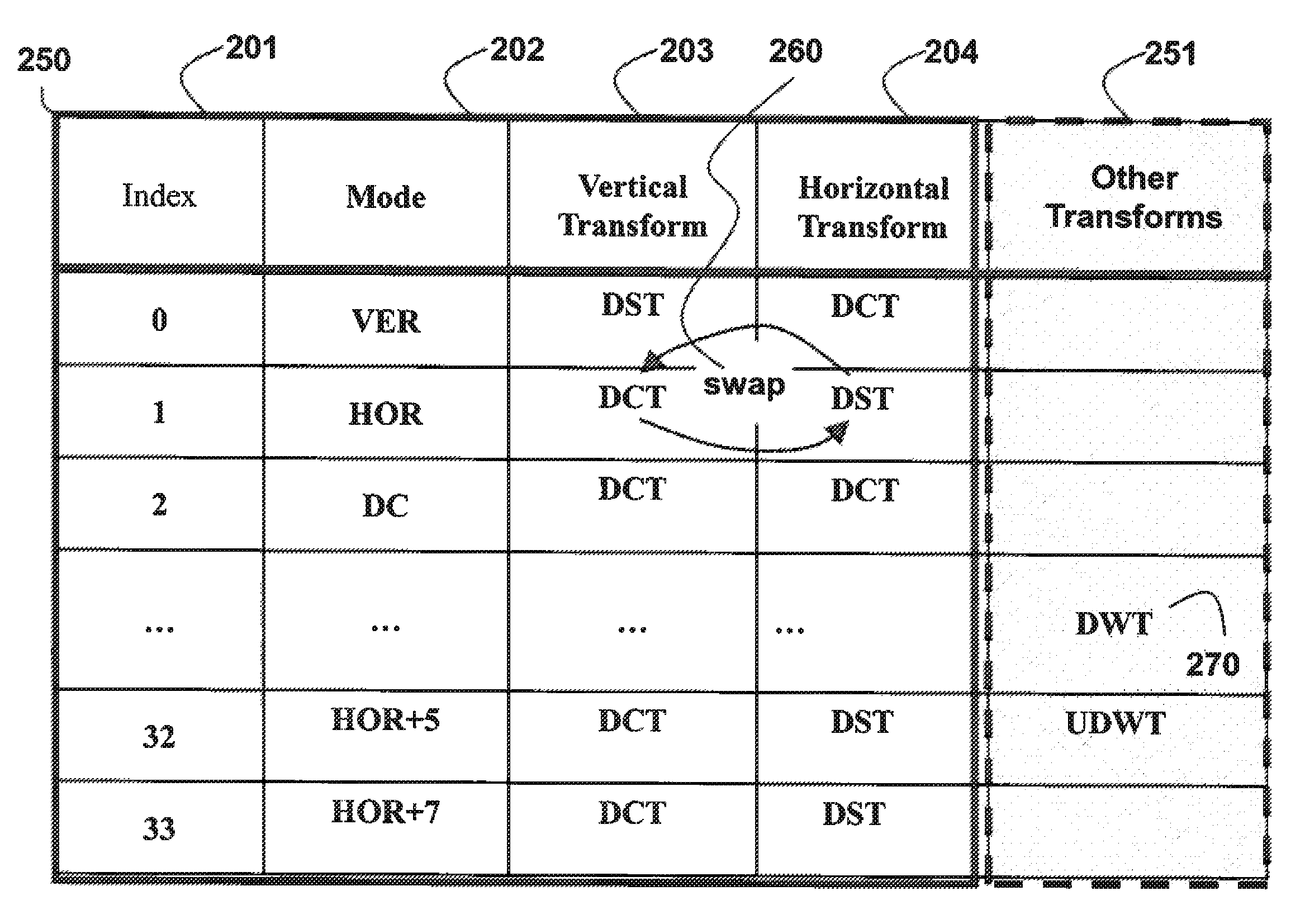
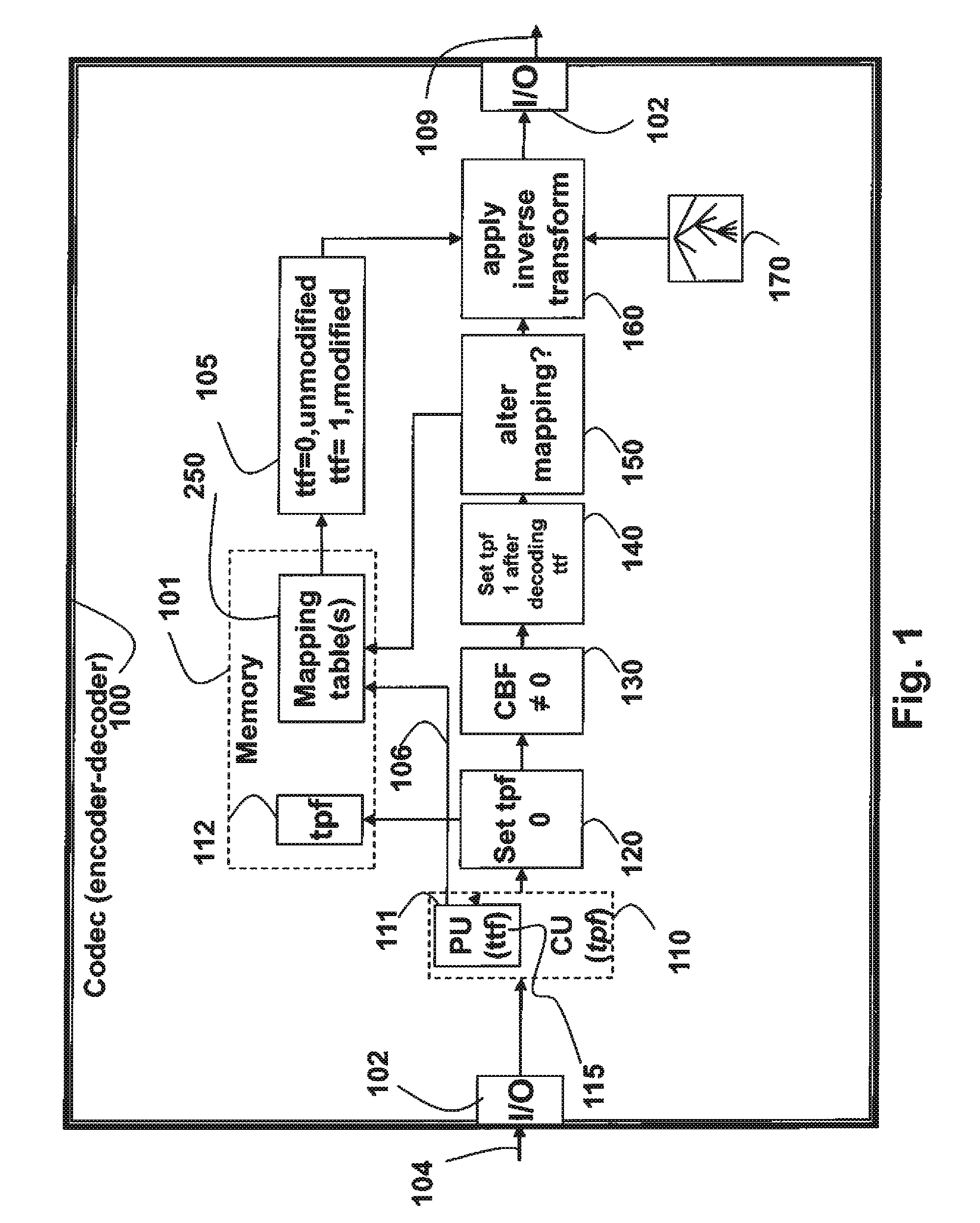
[0028]In this embodiment, the steps above are applied, and if the ttf for a TU is one (1), then a DCT in the mapping table becomes a DST, and a DST becomes a DCT. In other words, if the original mapping table specifies that a DCT is used as the horizontal transform for a given prediction mode, then a DST is used if the ttf is one (1). Similarly, a DCT is used instead of a DST. If the transform-toggle is zero (0) set, then the original mapping is used.

embodiment 2

[0029]This embodiment is similar to Embodiment 1, except mapping is altered only for Intra prediction directions for which both the horizontal and vertical transforms are different. Thus, if the table specifies that the DCT is used for both transforms, then the mapping is not altered. If the table specifies that a first set of horizontal DCT and vertical DST is used, then the mapping is altered so that a second set of horizontal DST and vertical DCT is used. The end effect is that the transforms in first set are swapped 260 to effectively result in the second set, as shown in FIG. 2B.

embodiment 3

[0030]This embodiment is similar to Embodiment 1, except that the mapping of the first set is altered to the second set only for Intra prediction directions for which both the horizontal and vertical transforms are identical. This maps a 2-D ACT to a 2-D DST, and a 2-D DST to a 2-D DCT, without altering any 2-D transform where the horizontal and vertical transform types are different.


PUM


Abstract

A method codes pictures in a bitstream, wherein the bitstream includes coded pictures to obtain data for associated TUs and data for generating a transform tree, and a partitioning of coding units (CUs) into Prediction Units (PUs), and data for obtaining prediction modes or directions associated with each PU. One or more mapping tables are defined, wherein each row of each table has an associated index and a first set of transform types to be used for applying an inverse transformation to the data in TU. The first set of transform types is selected according to an index, and then a second set of transform types is applied as the inverse transformation to the data, wherein the second set of transform types is determined according to the first set of transform types and a transform-toggle flag (ttf) to obtain a reconstructed prediction residual.

Description

RELATED APPLICATION[0001]This U.S. Patent Application is related to U.S. patent application Ser. No. 13 / 169,959 “Method for Coding Pictures Using Hierarchical Transform Units,” filed by Cohen et al. on Jun. 27, 2011, incorporated herein by reference.FIELD OF THE INVENTION[0002]The invention relates generally to coding pictures, and more particularly to methods for coding pictures using selected transforms in the context of encoding and decoding pictures.BACKGROUND OF THE INVENTION[0003]For the High Efficiency Video Coding (HEVC) standard currently under consideration by the ISO and ITU standards organizations, Discrete Cosine Transforms (DCT) and / or Discrete Sine Transforms (DST) are applied to 4×4 blocks of data. The decision as to which transform types to apply horizontally and vertically is defined by a look-up table, see FIG. 2A, which that maps an indexed Intra prediction direction to a horizontal transform type and a vertical transform type. This mapping is described in “CE7: ...

Claims


Application Information

Patent Timeline
Patent Type & Authority Patents(United States)
IPC IPC(8): H04N7/12H04N19/10H04N19/102H04N19/11H04N19/12H04N19/159H04N19/61
CPCH04N7/52H04N19/60H04N19/12H04N19/159H04N19/61H04N19/11H04N19/10H04N19/122
Inventor COHEN, ROBERT A.VETRO, ANTHONY
Owner MITSUBISHI ELECTRIC RES LAB INC
Why Eureka
Try Eureka