Apparatus and method for detecting target object

a target object and apparatus technology, applied in the field of apparatus and methods for detecting targets, can solve the problems of inability to completely prevent the influence of interference, inability to accurately display the target object by the radar apparatus of the ship, and difficulty in determining the effective pulse transmission method by comparing with all the other radars in advance, so as to minimize the number of sampling points and minimize the effect of sampling points

Active Publication Date: 2016-05-10
FURUNO ELECTRIC CO LTD
View PDF10 Cites 49 Cited by
  • Summary
  • Abstract
  • Description
  • Claims
  • Application Information

AI Technical Summary

Benefits of technology

[0006]The present invention is made in view of the above situation, and provides a target object detection apparatus that uses a transmission signal with wide pulse width (e.g., a fixed radar), reduces influence of an interference wave, and can appropriately catch a target object that is supposed to be detected originally.
[0008]The device can be widely applied to an apparatus for detecting a target object by transmitting a transmission pulse and receiving a reflection wave from the target object, and based on an evaluation of the reception signal, the device adjusts a transmission timing of the transmission pulse to further reduce an influence from an interference wave.
[0027]According to another aspect of the present invention, a method of detecting a target object by repeatedly transmitting a transmission pulse and receiving a reception signal from the target object is provided. The method includes repeatedly transmitting the transmission pulse at a transmission timing, receiving the reception signal at a reception timing set based on the transmission timing, and setting a plurality of different parameters for controlling the transmission timing, the plurality of different parameters including the parameter for determining the transmission timing. The method also includes determining, based on each of the plurality of different parameters, whether an amplitude value of the reception signal exceeds a predetermined threshold at every sampling point, and counting the number of sampling points at which the amplitude value of the reception signal exceeds the threshold. The method further includes selecting the parameter from the plurality of different parameters to minimize the number of sampling points, and controlling the transmission timing and the reception timing from the target object, based on the selected parameter.

Problems solved by technology

However, when radio waves are discharged from another radar apparatus existing around the radar apparatus of the ship, there is a case where the target object cannot be displayed accurately by the radar apparatus of the ship.
Therefore, determining an effective pulse transmission method by comparing with all the other radars in advance is extremely difficult.
In particular, since fixed radars have significantly larger pulse widths compared to the conventional magnetron radars, influence of interference cannot be completely prevented even by adding jitter in many cases.

Method used


Image

  • Apparatus and method for detecting target object
  • Apparatus and method for detecting target object
  • Apparatus and method for detecting target object

Examples


first embodiment

[First Embodiment]

[0038]Hereinafter, a target object detection apparatus according to a first embodiment of the present invention is described with reference to the appended drawings.

[0039]The target object detection apparatus of the present invention can be widely applied to apparatuses that detect target objects by transmitting transmission pulses and receiving reflection signals from the target objects. In this embodiment, a radar apparatus for detecting a target object by transceiving electromagnetic waves is described as an example. The target object detection apparatus may also be applied to sonars for detecting a target object underwater by transceiving ultrasonic waves.

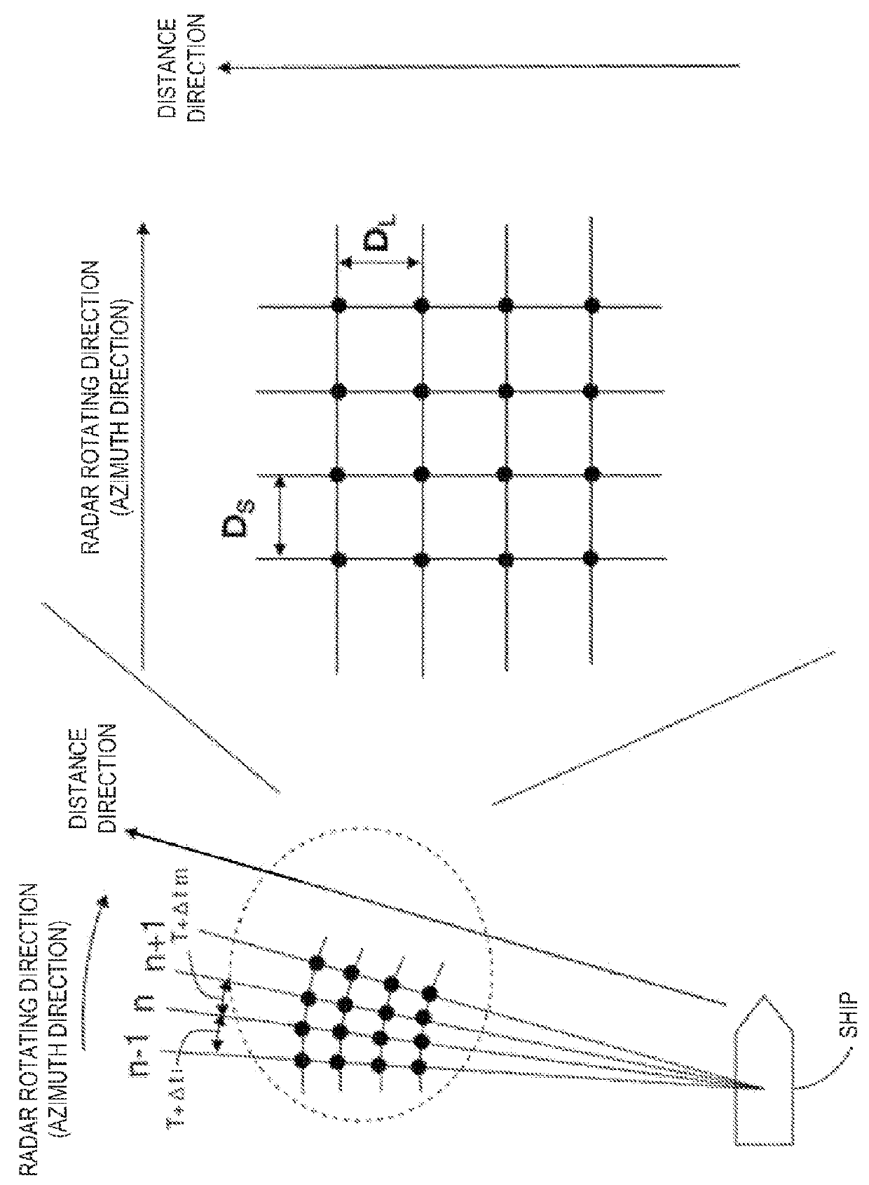
[0040]A radar apparatus according to this embodiment is a ship radar apparatus provided in, for example, a ship (hereinafter, referred to as “the ship”) and for detecting a target object such as another ship, a buoy, or a bird that is on the sea.

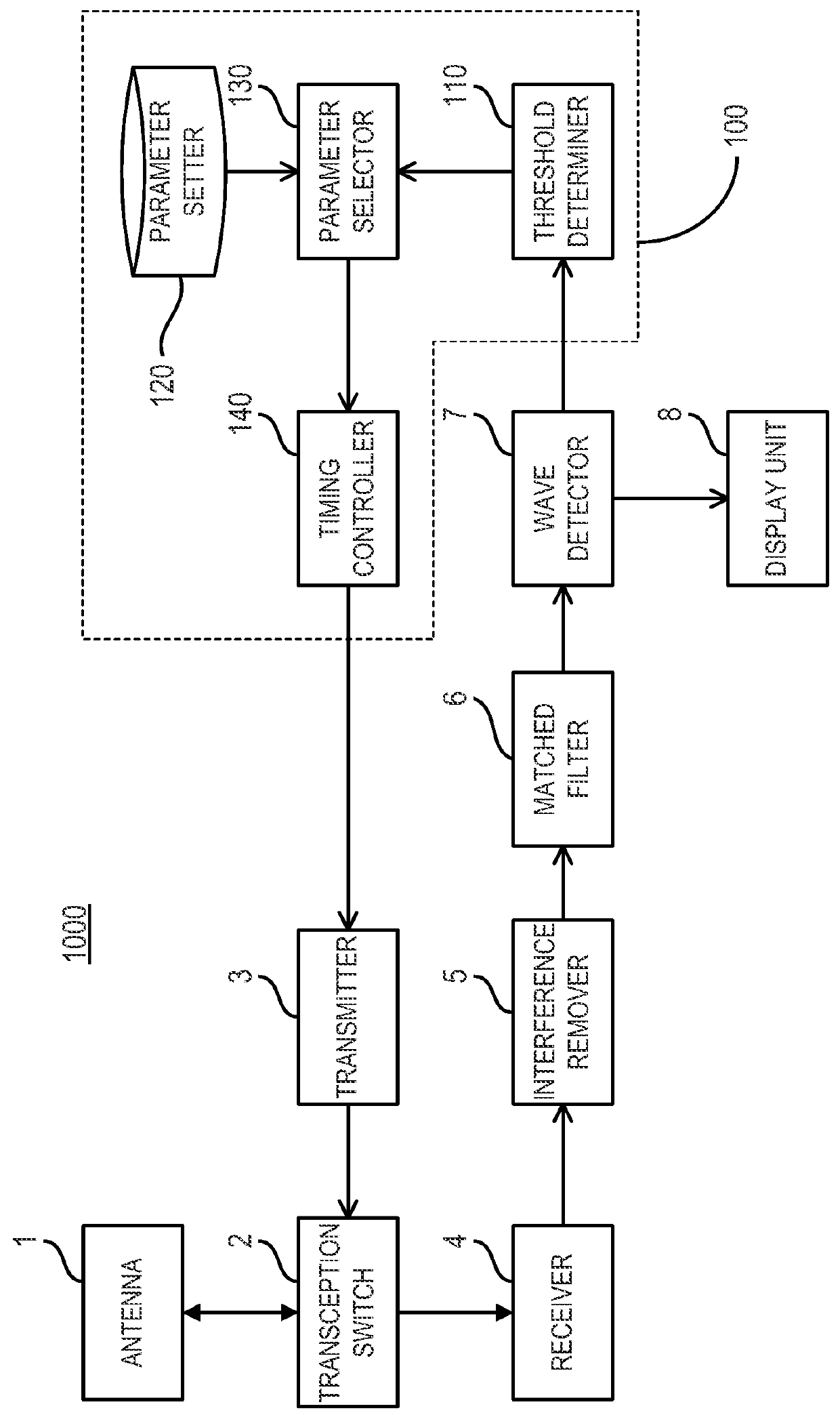
[0041]A configuration of a radar apparatus 1000 of this embodimen...


PUM


Abstract

A target object detection apparatus is provided. The apparatus includes a transmitter, a receiver, a threshold determiner, a parameter setter, a parameter selector, and a timing controller. The transmitter repeatedly transmits a transmission pulse at a transmission timing. The receiver receives a reception signal at a reception timing set based on the transmission timing. The threshold determiner determines whether an amplitude value of the reception signal exceeds a predetermined threshold at every sampling point and counts the number of sampling points at which the amplitude value of the reception signal exceeds the threshold. The parameter setter sets a plurality of different parameters for controlling the transmission timing. The parameter selector selects the parameter from the parameter settings, to minimize the number of sampling points counted by the threshold determiner. The timing controller controls the transmission timing, based on the parameter selected by the parameter selector.

Description

CROSS-REFERENCE TO RELATED APPLICATION(S)[0001]The application claims priority under 35 U.S.C. §119 to Japanese Patent Application No. 2012-140097, which was filed on Jun. 21, 2012, and Japanese Patent Application No. 2013-078980, which was filed on Apr. 4, 2013 the entire disclosure of which are hereby incorporated by references.TECHNICAL FIELD[0002]The present invention generally relates to an apparatus and method for detecting a target object.BACKGROUND OF THE INVENTION[0003]Among target object detection apparatuses, for example, a radar apparatus equipped on a ship generally detects target objects (e.g., other ships and buoys on the sea) by discharging radio waves and receiving reflection waves, and displays the detected target object on a display.[0004]However, when radio waves are discharged from another radar apparatus existing around the radar apparatus of the ship, there is a case where the target object cannot be displayed accurately by the radar apparatus of the ship. Thi...

Claims


Application Information

Patent Timeline
Patent Type & Authority Patents(United States)
IPC IPC(8): G01S7/02G01S7/28G01S13/22
CPCG01S7/2813G01S7/023G01S13/22G01S13/428G01S13/937G01S7/0235
Inventor MAENO, HITOSHIASADA, YASUNOBU
Owner FURUNO ELECTRIC CO LTD
Why Eureka
Try Eureka